Camera

a technology of camera and shutter curtain, applied in the field of camera, can solve the problem of insufficient accuracy and achieve the effect of achieving higher accuracy and more accurate measurement of shutter curtain traveling accuracy

Inactive Publication Date: 2007-07-12
CANON KK
View PDF6 Cites 9 Cited by
  • Summary
  • Abstract
  • Description
  • Claims
  • Application Information

AI Technical Summary

Benefits of technology

[0006] The present invention has therefore been made in consideration of the above problems, and has as its object to measure the traveling accuracy of shutter curtains more accurately and correct the traveling accuracy of the shutter curtains with higher accuracy.

Problems solved by technology

In addition, since measurement is not made on a portion of the shutter which is actually used for recording, sufficient accuracy cannot be obtained.

Method used


Image

  • Camera
  • Camera
  • Camera

Examples


first embodiment

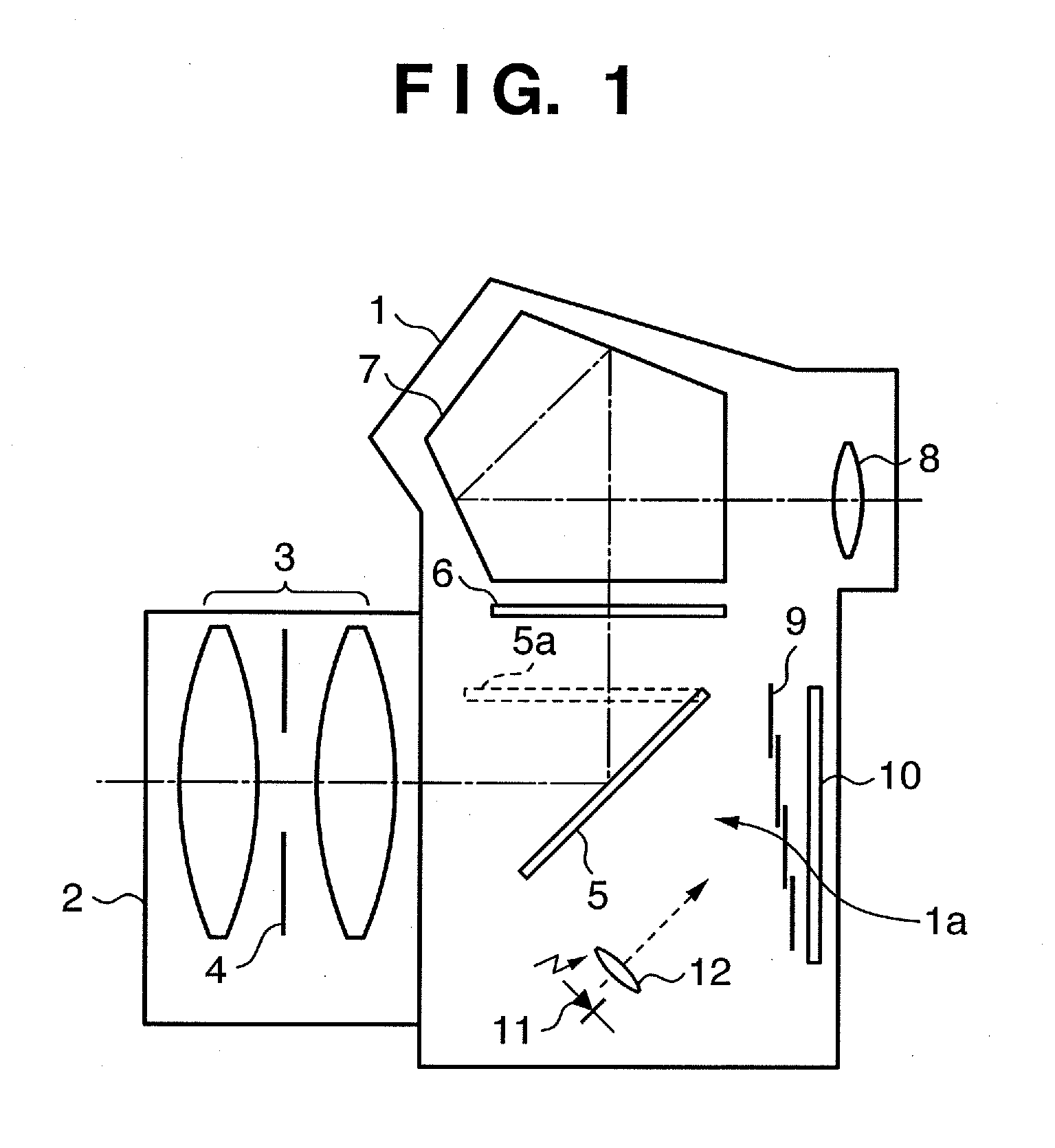
[0023]FIG. 1 is a cross-sectional view showing the schematic arrangement of a camera according to the first embodiment of the present invention.

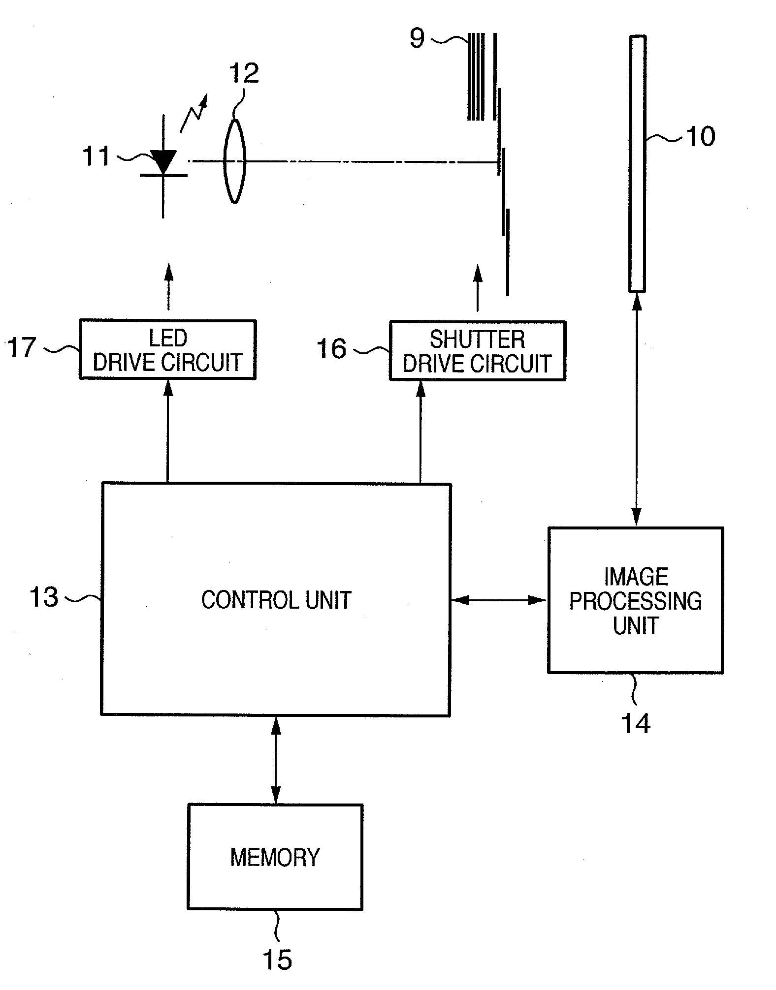
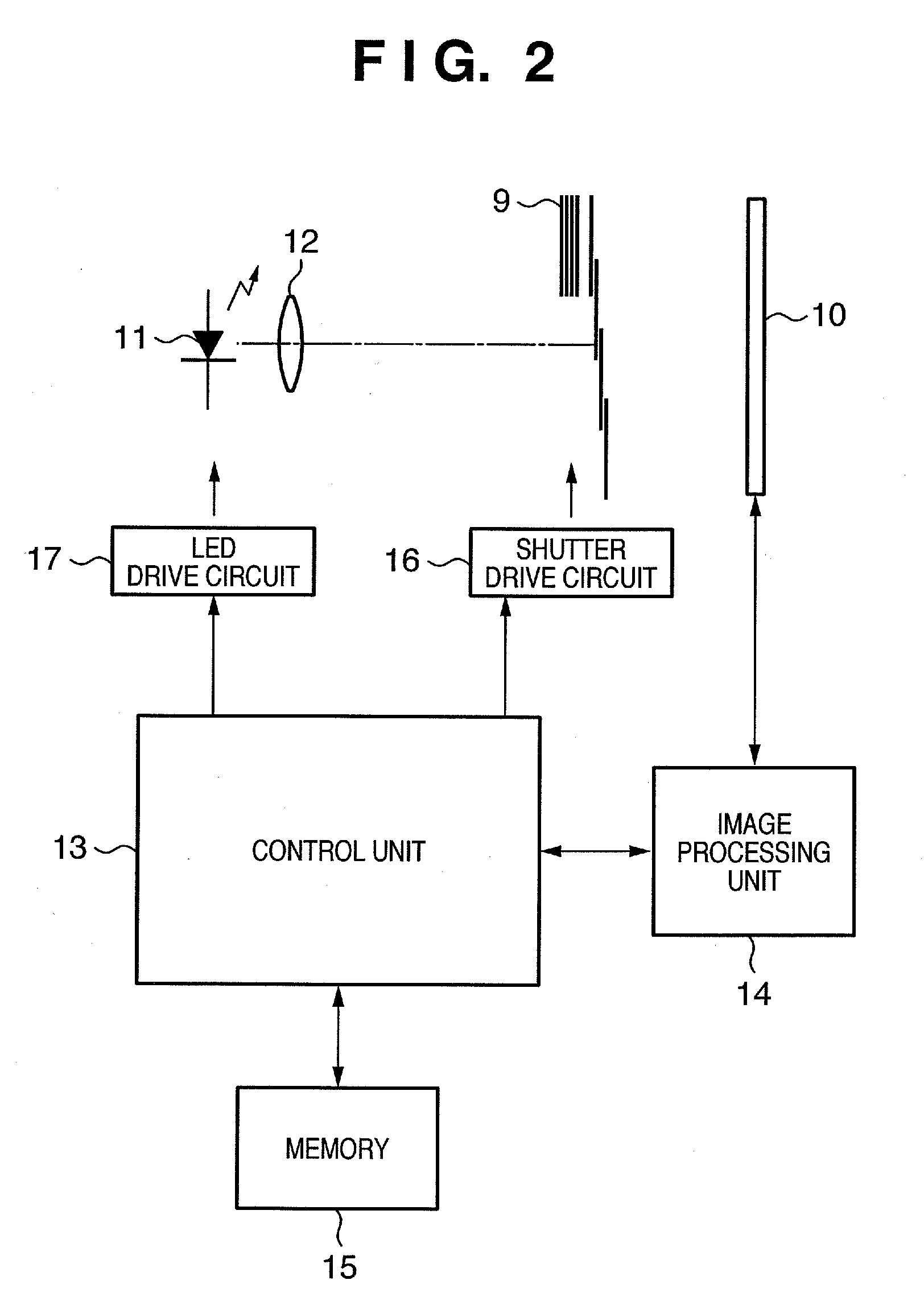
[0024] Referring to FIG. 1, reference numeral 1 denotes a camera body; 2, an interchangeable lens which is detachably mounted on the camera body 1; 3, a photographing lens built into the interchangeable lens 2; 4, a diaphragm for controlling the amount of light passing through the photographing lens 3; 5, a main mirror for reflecting light passing through the photographing lens 3 and guiding the light to the finder; 6, a screen for projecting an object image upon receiving light from an object through the main mirror 5; 7, a pentagonal roof prism for guiding the image projected on the screen 6 onto the operator side; 8, an eyepiece lens for the observation of the image projected on the screen 6; and 9, a shutter for performing exposure control with respect to light entering through the photographing lens 3 at the time of recording or light ...

second embodiment

[0095]FIG. 10 is a view showing the schematic arrangement of a camera according to the second embodiment of the present invention.

[0096] Referring to FIG. 10, reference numeral 51 denotes a camera body; 52, a light source unit mounted on an interchangeable lens mount which is detachably mounted on the camera body 51; 53, a light source such as an LED placed in the light source unit 52; 54, a projection lens for guiding light emitted from the light source 53 into the camera; and 55, a main mirror for reflecting light entering through the lens mount portion and guiding the light to the finder. The main mirror 55 flips up to the position indicated by the dotted line at the time of recording to ensure an optical path to a shutter 59 or image sensor 60.

[0097] Reference numeral 56 denotes a screen which receives light from an object through the main mirror 55 and projects an object image; 57, a pentagonal roof prism for guiding the image projected on the screen 56 onto the operator side...


PUM


Abstract

The invention includes an image sensor, a shutter which opens/closes by making a front curtain and a rear curtain travel, a light source which illuminates the image sensor, a control unit which performs control to make the front and rear curtains travel with a predetermined time shift to form a slit-like opening, and to make the light source emit light a predetermined period of time after the start time of traveling of the front and rear curtains, a detection unit which detects the deviation between the position of an image of the recorded slit-like opening and a predetermined reference position, a computation unit which calculates the error between the traveling start timing of the front and rear curtains on the basis of the detected deviation, and a correction unit which corrects the calculated error between the traveling start timing of the front and rear curtains.

Description

BACKGROUND OF THE INVENTION [0001] 1. Field of the Invention [0002] The present invention relates to a technique of detecting and correcting the traveling accuracy of the shutter of a camera. [0003] 2. Description of the Related Art [0004] Conventionally, as disclosed in Japanese Patent Application Laid-Open No. 6-208157, there is known a camera having a function of measuring the traveling accuracy of shutter curtains by measuring the passage times of the shutter curtains using an LED as a light source and a phototransistor which receives light from the LED. [0005] In the camera disclosed in Japanese Patent Application Laid-Open No. 6-208157, the light source and the light receiving unit need to be arranged outside the opening of the shutter used for recording, and hence the size of the shutter becomes large. In addition, since measurement is not made on a portion of the shutter which is actually used for recording, sufficient accuracy cannot be obtained. SUMMARY OF THE INVENTION [0...

Claims


Application Information

Patent Timeline
Patent Type & Authority Applications(United States)
IPC IPC(8): G03B7/00G03B9/36G03B9/62
CPCG03B9/62G03B9/36
Inventor KASHIYAMA, RITSUO
Owner CANON KK
Why Eureka
Try Eureka