Instruments and Methods For Manipulating A Spinal Rod

a technology of spinal rods and instruments, applied in the field of spinal rod manipulators, can solve the problems of difficult alignment and seating of rods into the receiving portion of adjacent fixation devices, difficult and time-consuming use, and other problems, to achieve the effect of improving the stability of use and reducing the difficulty of us

Inactive Publication Date: 2007-07-12
DEPUY SPINE INC (US)
View PDF52 Cites 83 Cited by
  • Summary
  • Abstract
  • Description
  • Claims
  • Application Information

AI Technical Summary

Problems solved by technology

While current spinal systems have proven effective, difficulties have been encountered in mounting rods, or other spinal connection elements, into the rod-receiving portion of various fixation devices.
In particular, it can be difficult to align and seat the rod into the rod receiving portion of adjacent fixation devices due to the positioning and rigidity of the vertebra into which the fixation device is mounted.
While several rod approximators are known in the art, some tend to be difficult and very time-consuming to use.

Method used


Image

  • Instruments and Methods For Manipulating A Spinal Rod
  • Instruments and Methods For Manipulating A Spinal Rod
  • Instruments and Methods For Manipulating A Spinal Rod

Examples


Embodiment Construction

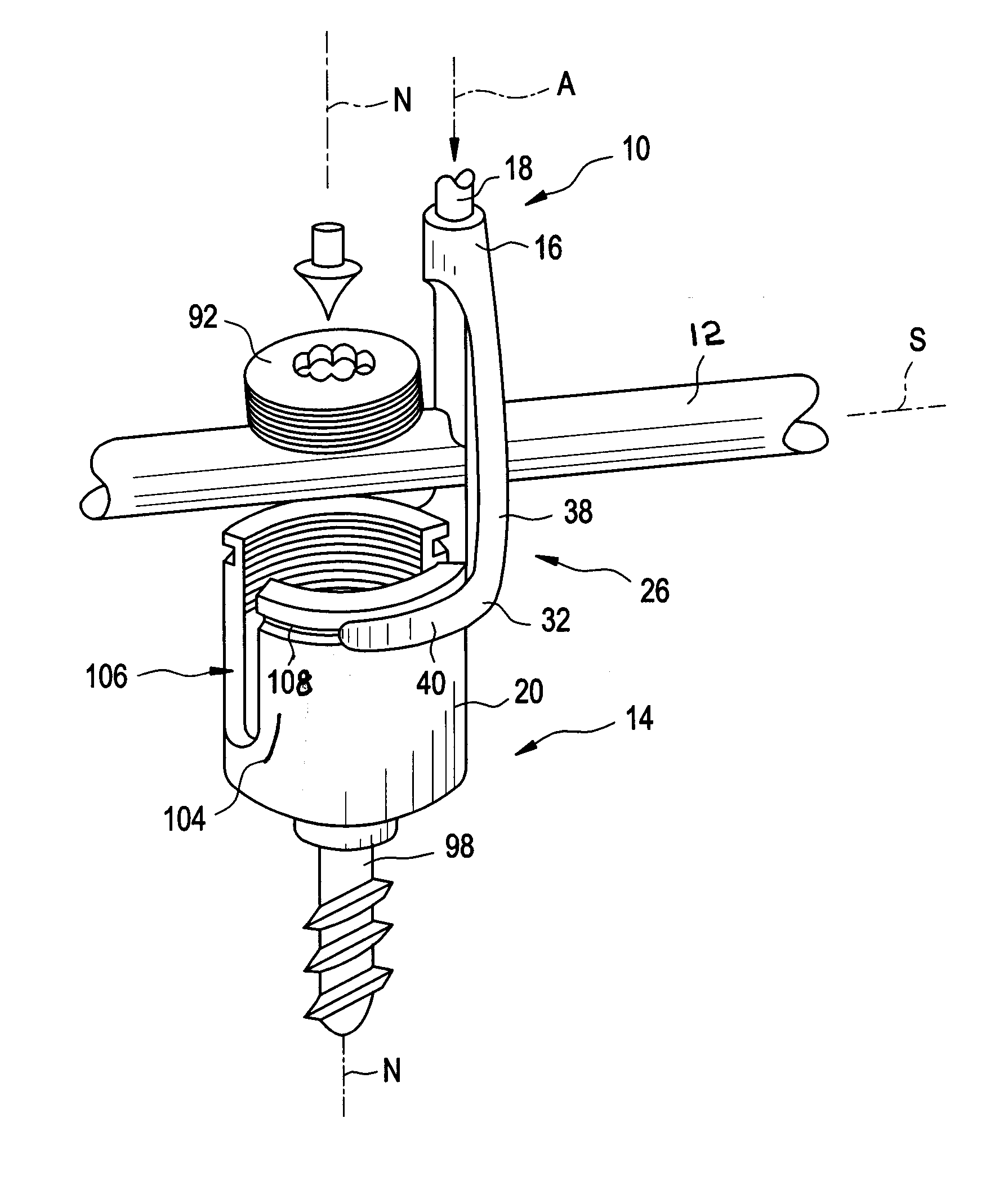
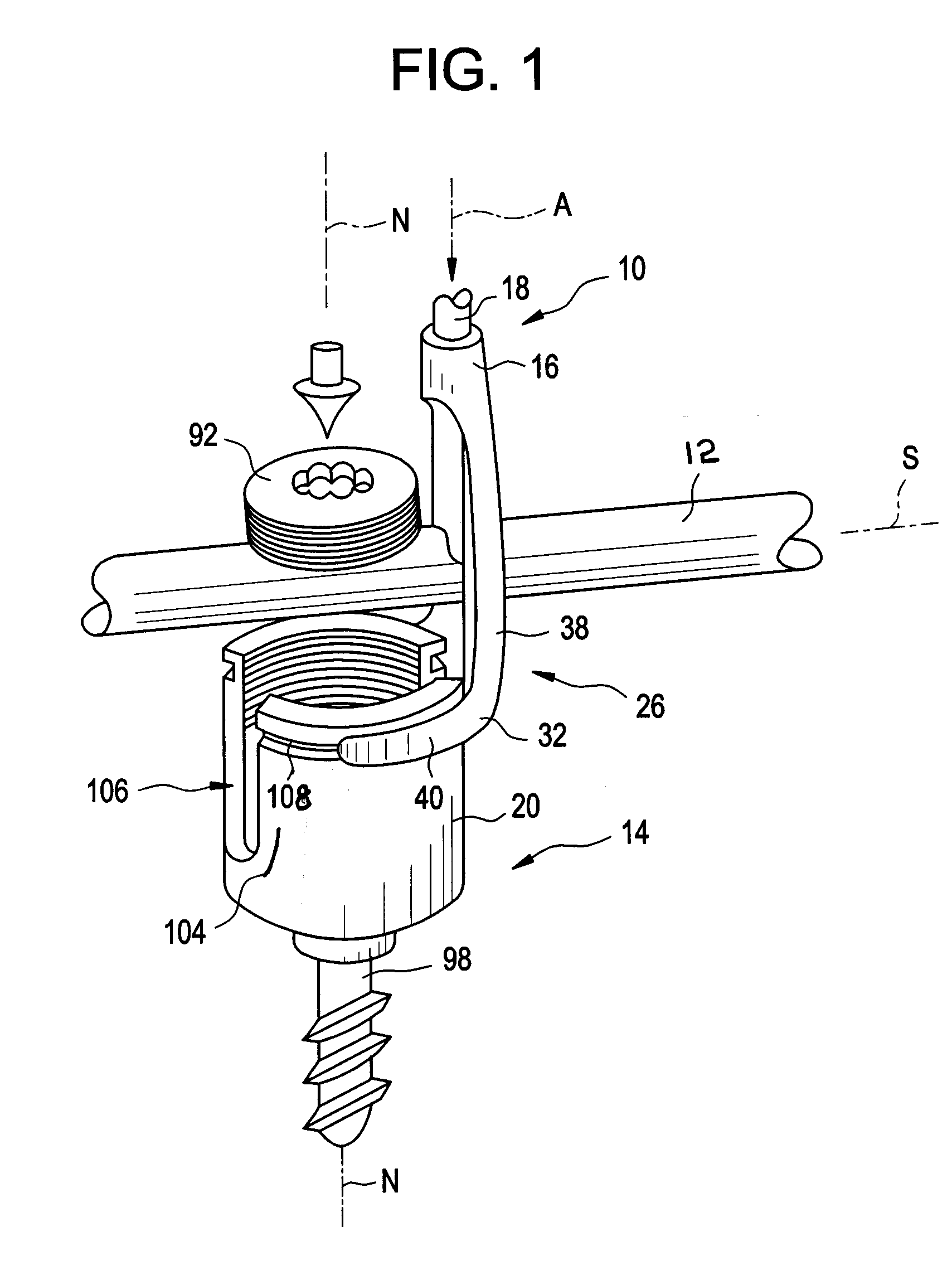
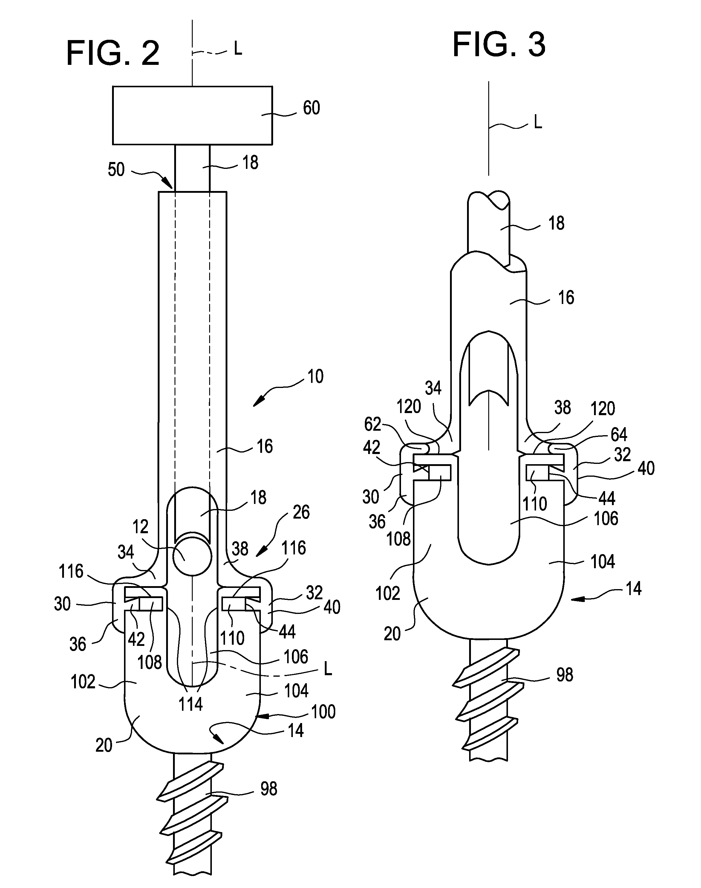
[0020] Certain exemplary embodiments will now be described to provide an overall understanding of the principles of the structure, function, manufacture, and use of the instruments and methods disclosed herein. One or more examples of these embodiments are illustrated in the accompanying drawings. Those of ordinary skill in the art will understand that the instruments and methods specifically described herein and illustrated in the accompanying drawings are non-limiting exemplary embodiments and that the scope of the present invention is defined solely by the claims. The features illustrated or described in connection with one exemplary embodiment may be combined with the features of other embodiments. Such modifications and variations are intended to be included within the scope of the present invention.

[0021] The articles “a” and “an” are used herein to refer to one or to more than one (i.e. to at least one) of the grammatical object of the article. By way of example, “an element...


PUM


Abstract

An instrument for manipulating a spinal rod relative to a bone anchor may include a first shaft and a first finger and a second finger provided at a distal end of the first shaft. The first finger may be spaced apart a distance from the second finger approximate to the outer diameter of the receiver member of the bone anchor. Each of the first finger and the second finger may include a projection extending along the length of the finger for engaging a groove provided on the receiver member of the bone anchor. The instrument may also include a second shaft that is movable relative to the first shaft in a direction parallel to the longitudinal axis of the first shaft to manipulate the spinal rod relative to the receiver member of the bone anchor.

Description

CROSS-REFERENCE TO RELATED APPLICATIONS [0001] This application claims priority to U.S. Provisional Patent Application No. 60 / 731,072 filed Oct. 28, 2005, which is incorporated herein by reference.Background [0002] Spinal systems may be used in orthopedic surgery to align and / or fix a desired relationship between adjacent vertebrae. Such systems typically include a spinal connection element, such as a relatively rigid fixation rod or plate, a relatively flexible tether or cable, or a dynamic connection element that is coupled to adjacent vertebrae by attaching the element to various anchoring devices, such as hooks, bolts, wires, or screws. The spinal connection element can have a predetermined contour that has been designed according to the properties of the target implantation site, and once installed, the spinal connection element holds the vertebrae in a desired spatial relationship, either until desired healing or spinal fusion has taken place, or for some longer period of time...

Claims


Application Information

Patent Timeline
Patent Type & Authority Applications(United States)
IPC IPC(8): A61F2/30
CPCA61B17/7086A61B17/7032
Inventor WHIPPLE, DALE
Owner DEPUY SPINE INC (US)
Why Eureka
Try Eureka