Tool

a hip joint and tool technology, applied in the field of tools, can solve the problems of re-reform of bone, end up unable to function, and further erosion, and achieve the effect of reducing pain, reducing pain, and reducing pain

Inactive Publication Date: 2007-07-12
FINSBURY DEV
View PDF30 Cites 197 Cited by
  • Summary
  • Abstract
  • Description
  • Claims
  • Application Information

AI Technical Summary

Benefits of technology

[0047] A flag and/or guide pin may be included at the distal end of the support arm and where present will generally extend below the position of the ring. The flag and/or guide pin may be integral with the support arm or may be provided as a separate fitting. This flag or pin will serve as a visual guide to assist the surgeon to check that the jig is in the correct alignment with the medial side of the femoral neck to ensure the correct valgus-varus alignment and the correct ante-version an

Problems solved by technology

Diseases such as rheumatoid- and osteo-arthritis can cause erosion of the cartilage lining of the acetabulum so that the ball of the femur and the hip bone rub together causing pain and further erosion.
Bone erosion may cause the bones themselves to attempt to compensate for the erosion which may result in the bone being reshaped.
This misshapen joint may cause pain and may eventually cease to function altogether.
Failure to position the alignment guide correctly may have the disastrous effect of allowing the machining of the cylinder of the head during the shaping procedure to “notch” into the neck of the femur.
This will predispose the bone to early failure on load bearing.
Whilst sufficient force to insert the prosthesis can be provided by striking with a tool of this type, it is difficult to control the amount of force applied.
In addition, the use of a tool which is separate from the prosthesis means that it is difficult to ensure that the force is applied in the o

Method used


Image

  • Tool
  • Tool
  • Tool

Examples


Embodiment Construction

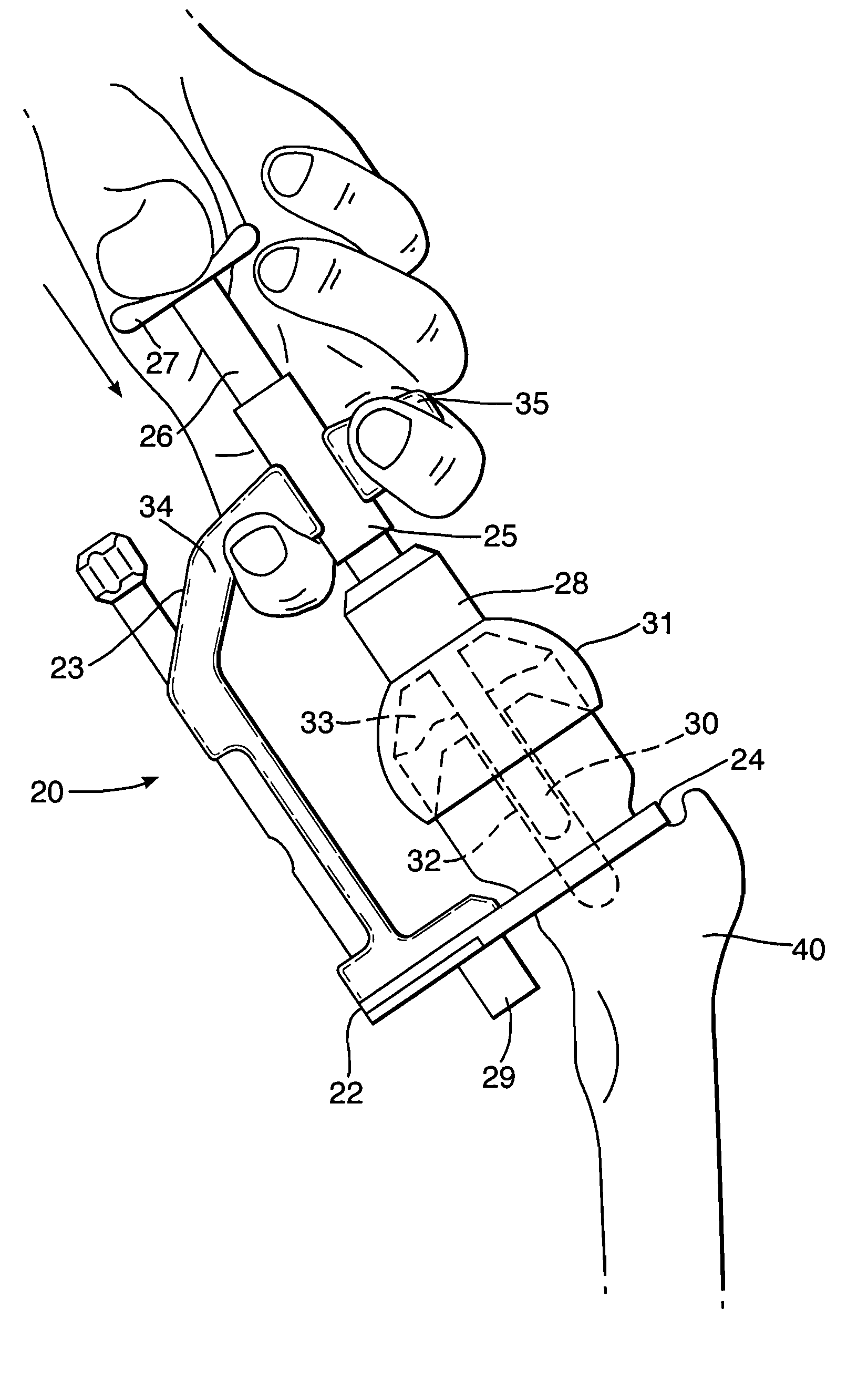
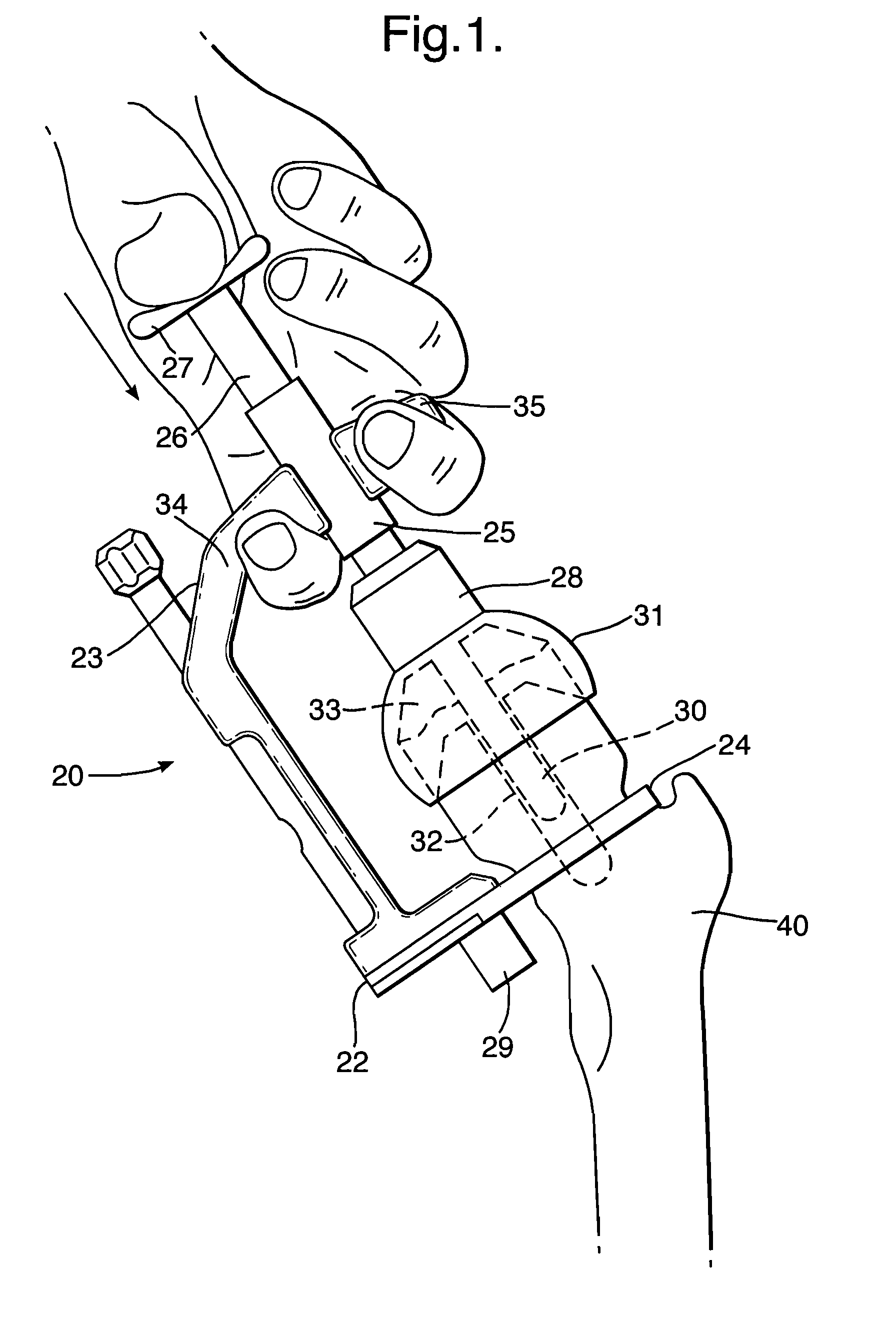
[0059] As illustrated in FIG. 1, the jig 20 of one embodiment of the present invention comprises a support arm having a distal 22 and a proximal 23 end a ring 24 is located at the distal end of the arm and extends therefrom such that it is at right angles to the plane of the arm. However, it will be noted that the arm is shaped to allow the arm, in use, to fit around the femoral head a static member in the form of a collar 25 located at the proximal end of the support arm. An applicator member 26 is a sliding fit in the collar. A thumb plate 27 is located at the proximal end of the applicator member and a connector means 28 in the form of a plastics plunger is located at the distal end.

[0060] A flag 29 may be present to assist the surgeon to visually confirm that the alignment guide is in the desired position.

[0061] A shaped region 34 of the support arm and a handle 35 are provided to enable the fingers to be positioned in use.

[0062] In use the ring is located around the neck of ...


PUM


Abstract

A jig for the application of a femoral head resurfacing prosthesis to a prepared femoral head wherein the jig comprises: at least one support arm having a proximal and a distal end; a jaw located at the distal end of the support arm and angled to the plane of the support arm; a static member located at the proximal end of the or each support arm; an applicator member associated with the static member and movable with respect thereto; and a connector means to enable the applicator member in use to interact with an outer surface of a femoral head resurfacing prosthesis; the applicator member comprising operating means to enable the applicator member to be moved from a first upper position to a second lower position.

Description

CROSS-REFERENCE TO RELATED APPLICATION [0001] This application claims priority to foreign application UK Pat. App. No. 0521173.5 filed Oct. 18, 2005, which is hereby incorporated by reference. FIELD OF THE INVENTION [0002] The present invention relates to a tool for use in hip resurfacing operations. More particularly, it relates to a tool for assisting in the insertion of a replacement femoral head. BACKGROUND OF THE INVENTION [0003] The efficient functioning of the hip joints is extremely important to the well being and mobility of the human body. Each hip joint is comprised by the upper portion of the upper leg bone (femur) which terminates in an offset bony neck surmounted by a ball-headed portion which rotates within a socket, known as the acetabulum, in the pelvis. Diseases such as rheumatoid- and osteo-arthritis can cause erosion of the cartilage lining of the acetabulum so that the ball of the femur and the hip bone rub together causing pain and further erosion. Bone erosion...

Claims


Application Information

Patent Timeline
IPC IPC(8): A61B17/58A61F2/36A61F2/46
CPCA61F2/3601A61F2002/4628A61F2002/4627A61F2/4607
Inventor TUKE, MICHAEL ANTONY
Owner FINSBURY DEV
Why Eureka
Try Eureka