Washing machine

Active Publication Date: 2007-07-19
LG ELECTRONICS INC
View PDF29 Cites 22 Cited by
  • Summary
  • Abstract
  • Description
  • Claims
  • Application Information

AI Technical Summary

Benefits of technology

[0044] Firstly, the washing machine of the present invention has a direct connection motor and thus, has the effect of significantly reducing the generation of noise and failure as well as the loss of power. Also, with the use of a metallic bearing housing, the washing machine of the present invention is applicable to products having a high-temperature drying function, without the risk of thermal deformation.
[0045] Secondly, in the washing machine of the present invention, the rotor frame is made of an aluminum material and thus, has no risk of gathering rust thereon. This results in an increase in the durability of the motor. Furthermore, the rotor frame of the present invention has a magnet seating plane for achieving a highly efficient mounting operation of the magnet. Also, with the provision of vent holes having the function of moisture discharge and ventilation, it is possible to prevent overheating of the motor while protecting the motor from invasion of moisture. This consequently has the effect of increasing the reliability of the motor and e

Problems solved by technology

Such an indirect power transmission manner, however, has the following problems.
Thirdly, a necessity for a great number of elements for transmitting the drive force of the motor 5a to the drum 3, such as the motor pulley 18, the drum pulley 19, the belt 20, and the like, consequently, causes a complicated product assembling operation.
Fourthly, the above described great number of elements for transmitting the drive force of the motor 5a to the drum 3 may result in a proportional increase in the number of potential failure areas, and this has a problem of increasing the generation frequency of failures.
In conclusion, due to the above described power transmission manner in which the drive force of the motor 5ais indirectly transmitted to the drum 3 only by way of the motor pulley 18, the belt 20, and the drum pulley 19, the conventional drum type washing machine has problems of a high potentiality of failures and noise generation as well as excessive consumption of energy and seriously, may result in deterioration in washing performance thereof, etc.
However, forming the rotor frame by pressing the iron plate has a difficulty, due to characteristics of a press operation, to obtain a required accuracy, more particularly, concentricity, when the thickness of the

Method used


Image

  • Washing machine
  • Washing machine
  • Washing machine

Examples


first embodiment

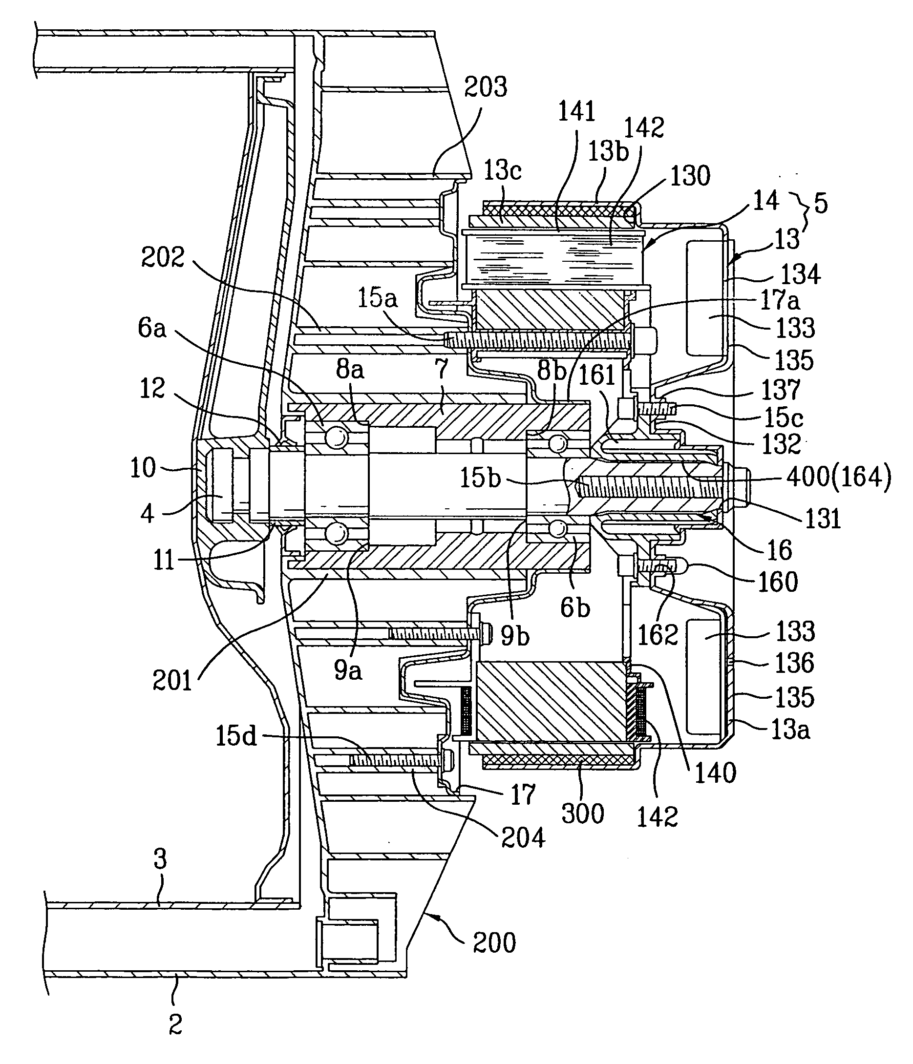
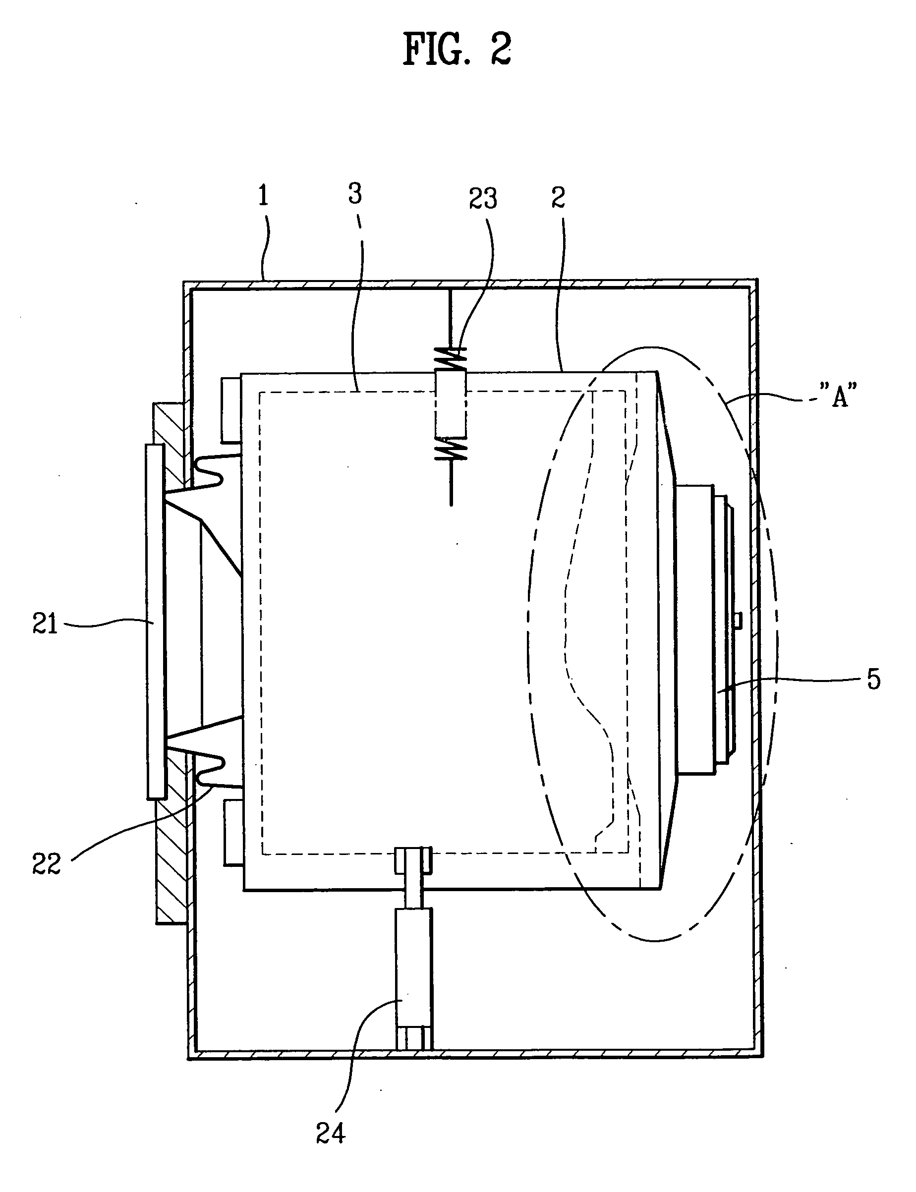
[0062] Now, the present invention will be described in detail with reference to FIGS. 2 to 7.

[0063]FIG. 2 is a longitudinal sectional view illustrating the configuration of a washing machine according to the present invention, and FIG. 3 is an enlarged detailed view of the portion “A” of FIG. 2, illustrating the configuration of a drive unit included in the washing machine according to the present invention.

[0064]FIG. 4 is a partially cut-away perspective view illustrating a rotor shown in FIG. 3, FIG. 5 is a perspective view illustrating a stator shown in FIG. 3, FIG. 6 is a perspective view illustrating a connector shown in FIG. 3, and FIG. 7 is a bottom perspective view of FIG. 6.

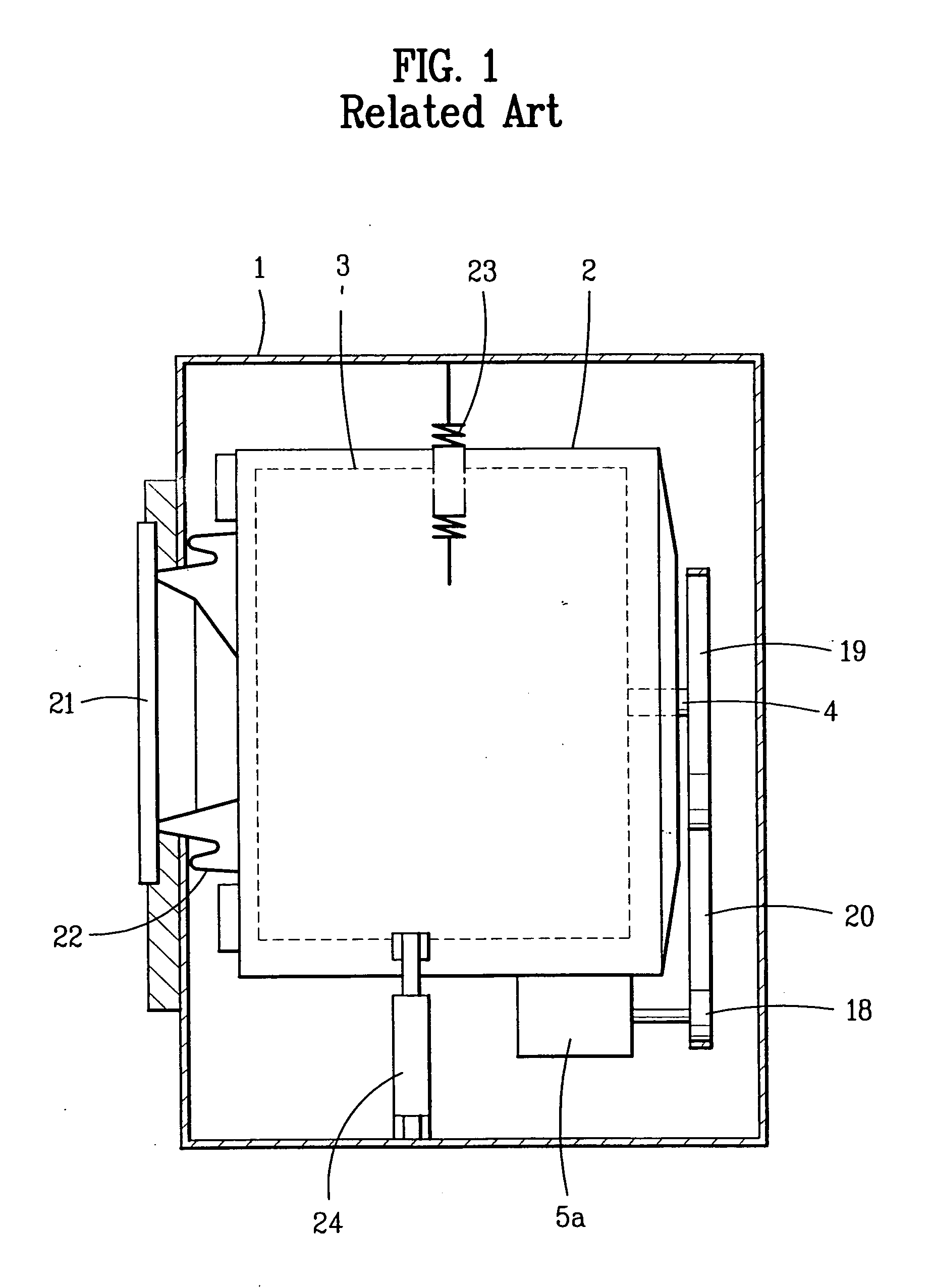
[0065] As shown in FIGS. 2 and 3, the washing machine according to the present embodiment comprises a tub 2 installed in a cabinet 1 and used to receive wash water therein, a drum 3 rotatably provided in the tub 2 and adapted to wash laundry received therein as it is rotated, a shaft 4 penetrated throu...

second embodiment

[0132] A difference between the present embodiment and the above described second embodiment is in that the protrusions 400 are formed at the back yoke and the recesses 401 are formed at the rotor frame. Accordingly, the back yoke is coupled fixedly to the rotor frame via engagement between the protrusions 400 and the recesses 401.

[0133] In conclusion, it will be appreciated by those skilled in the art that an important feature of the present invention is the provision of the protrusions 400 and the recesses 401 corresponding to each other. In other words, if the protrusions 400 are formed at the back yoke, the recesses may be formed at the rotor frame, and conversely, if the protrusions 400 are formed at the rotor frame, the recesses may be formed at the back yoke.

fourth embodiment

[0134] Hereinafter, a drum type washing machine according to the present invention will be described. The present embodiment may be easily understood with reference to FIG. 4.

[0135] The present embodiment has a feature in that the annular back yoke is coupled fixedly inside the side wall portion of the rotor frame as it is inserted into a mold of the rotor frame during the die casting of the rotor frame.

[0136] This has the effect of increasing the coupling strength between the back yoke and the rotor frame as a molten metal is solidified similar to an insert injection molding method.

[0137] The implementation of the above described method is possible because a fusion point of the rotor frame is lower than that of the back yoke.

[0138] To achieve a further increase in the coupling strength, the back yoke may be formed, at the outer surface thereof, with grooves (not shown) or protuberances (not shown), to provide the back yoke with a stepped outer surface.

[0139] Specifically, a plu...


PUM


Abstract

A washing machine, more particularly, an improvement in the structure of a drive unit included in a drum type washing machine is disclosed. The washing machine includes a tub for receiving wash water therein, a drum rotatably disposed in the tub and adapted to wash laundry received therein, a shaft penetrated through the tub to thereby be connected to the drum, the shaft being adapted to transmit a drive force of a motor to the drum, a stator coupled fixedly to a rear wall portion of the tub while being located on the rear wall portion, and an outer rotor including at least one magnet, an annular back yoke defining a magnetic path, and a rotor frame rotatably disposed at the outside of the stator. The rotor frame of the rotor is made of an aluminum material, and includes a side wall portion for supporting the magnet and the annular back yoke and a rear wall portion for transmitting a rotating force of the rotor to the shaft

Description

[0001] This application claims the benefit of the Korean Patent Application Nos. 10-2005-0115766, 10-2005-0115767, 10-2005-0115768 and 10-2005-0115769 filed on Nov. 30, 2005, which are hereby incorporated by reference as if fully set forth herein. BACKGROUND OF THE INVENTION [0002] 1. Field of the Invention [0003] The present invention relates to a washing machine, and more particularly, to an improvement in the structure of a drive unit included in a drum type washing machine. [0004] 2. Discussion of the Related Art [0005] Generally, drum type washing machines are designed to perform a washing operation by use of a frictional force between a drum and laundry as the drum is rotated by a drive force of a motor transmitted thereto in a state wherein the laundry is received in the drum together with wash water and detergent. The above described washing operation manner has several effects of causing damage to laundry as little as possible while preventing entangling of laundry and also...

Claims


Application Information

Patent Timeline
IPC IPC(8): D06F23/00
CPCD06F37/304H02K1/30H02K1/2786H02K1/2791H02K1/28
Inventor KIM, HYEOK DEOKCHOI, SOUNG BONG
Owner LG ELECTRONICS INC
Why Eureka
Try Eureka