Washing machine

a technology of washing machine and receptacle, which is applied in the direction of washing machine with receptacle, other washing machines, textiles and paper, etc., can solve the problems of increasing the generation frequency of failures, increasing the number of potential failure areas, and complicated product assembly operation, so as to reduce noise and failure generation, and without the risk of thermal deformation

Inactive Publication Date: 2007-06-07
LG ELECTRONICS INC
View PDF3 Cites 73 Cited by
  • Summary
  • Abstract
  • Description
  • Claims
  • Application Information

AI Technical Summary

Benefits of technology

[0038] Firstly, the washing machine of the present invention has a direct connection motor and thus, has the effect of significantly reducing the generation of noise and failure as well as the loss of power. Also, with the use of the metallic bearing housing, the washing machine of the present invention is applicable to products having a high-temperature drying function, without the risk of thermal deformation.
[0039] Secondly, in the washing machine of the present invention, the rotor frame is made of an aluminum material and thus, has no risk of gathering rust thereon. This results in an increase in the durability of the motor.
[0040] Thirdly, the rotor frame of the present invention has a magnet seating plane for achieving a highly efficient mounting operation of the magnet. Also, with the provision of vent holes having the function of moisture discharge and ventilation, it is possible to prevent overheating of the motor while protecting the motor from invasion of moisture. This consequently has the effect of increasing the reliability of the motor and extending the lifespan of the motor.
[0041] Fourthly, according to the present invention, the rotor frame is formed by die casting an aluminum material. Accordingly, the rotor frame can be manufactured with a simplified manner while guaranteeing an improved processability required for any subsequent process. Also, forming the rotor frame by use of a light-weight material is efficient to minimize the power loss of the motor due to the inertia force of the rotor frame.
[0042] Fifthly, the aluminum rotor frame provides a flexibility to ensure freely change in the thickness of the back yoke in views of diversification of products. This enables an increase in the overall thickness of the rotor frame and consequently, the rotor frame is free from unwanted fluctuation during rotation thereof, thus resulting in reduced noise and vibration. In addition, the change possibility of the thickness is advantageously applicable for the sake of reinforcing the strength of the rotor frame.

Problems solved by technology

Such an indirect power transmission manner, however, has the following problems.
Thirdly, a necessity for a great number of elements for transmitting the drive force of the motor 5a to the drum 3, such as the motor pulley 18, the drum pulley 19, the belt 20, and the like, consequently, causes a complicated product assembling operation.
Fourthly, the above described great number of elements for transmitting the drive force of the motor 5a to the drum 3 may result in a proportional increase in the number of potential failure areas, and this has a problem of increasing the generation frequency of failures.
In conclusion, due to the above described power transmission manner in which the drive force of the motor 5a is indirectly transmitted to the drum 3 only by way of the motor pulley 18, the belt 20, and the drum pulley 19, the conventional drum type washing machine has problems of a high potentiality of failures and noise generation as well as excessive consumption of energy and seriously, may result in deterioration in washing performance thereof, etc.
However, forming the rotor frame by pressing the iron plate has a difficulty, due to characteristics of a press operation, to obtain a required accuracy, more particularly, concentricity, when the thickness of the iron plate exceeds a predetermined value.
On the other hand, when the rotor frame is formed by use of an iron plate having a thickness less than the predetermined value, there is a problem in that the rotor frame cannot obtain a required strength and may fluctuate during rotation.
Accordingly, when the rotor frame serving as the back yoke has a small thickness, there is a limit to increase the output of a motor even if the amount of current is increased to obtain a strong output.
Consequently, the attempt to form the rotor frame having the function of the back yoke by use of the iron plate in views of diversification of products reaches a limit due to the above described thickness problem of the rotor frame.
Also, due to characteristics of the iron plate, there is a risk in that the rotor frame tends to gather rust on its surface easily.
The rust may cause deterioration in the strength of the rotor frame and in the worst case, there is a risk in that rust powder that falls from the rotor frame is attached in an air gap between the magnet and the stator, thereby acting to restrict rotation of the rotor.
In addition, the rotor frame, made of the iron plate, has a difficulty in the implementation of any subsequent process for improving accuracy and other processes.

Method used


Image

  • Washing machine
  • Washing machine
  • Washing machine

Examples


first embodiment

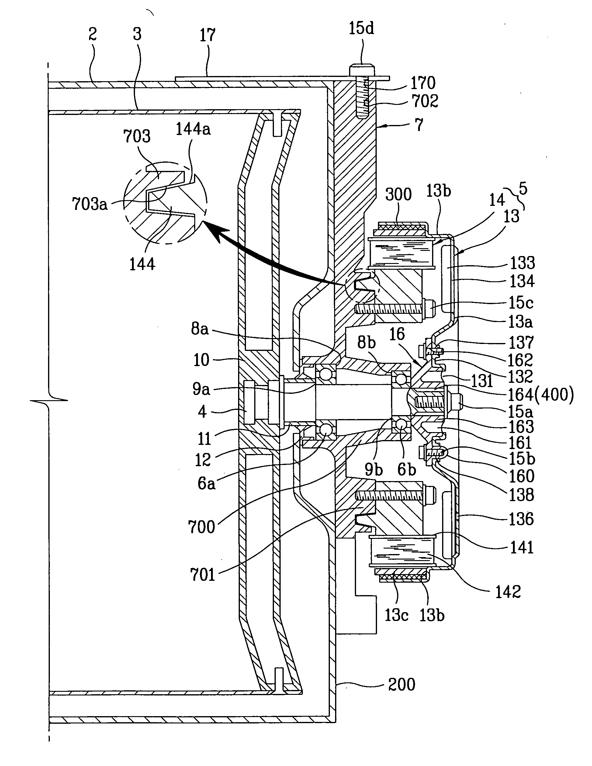
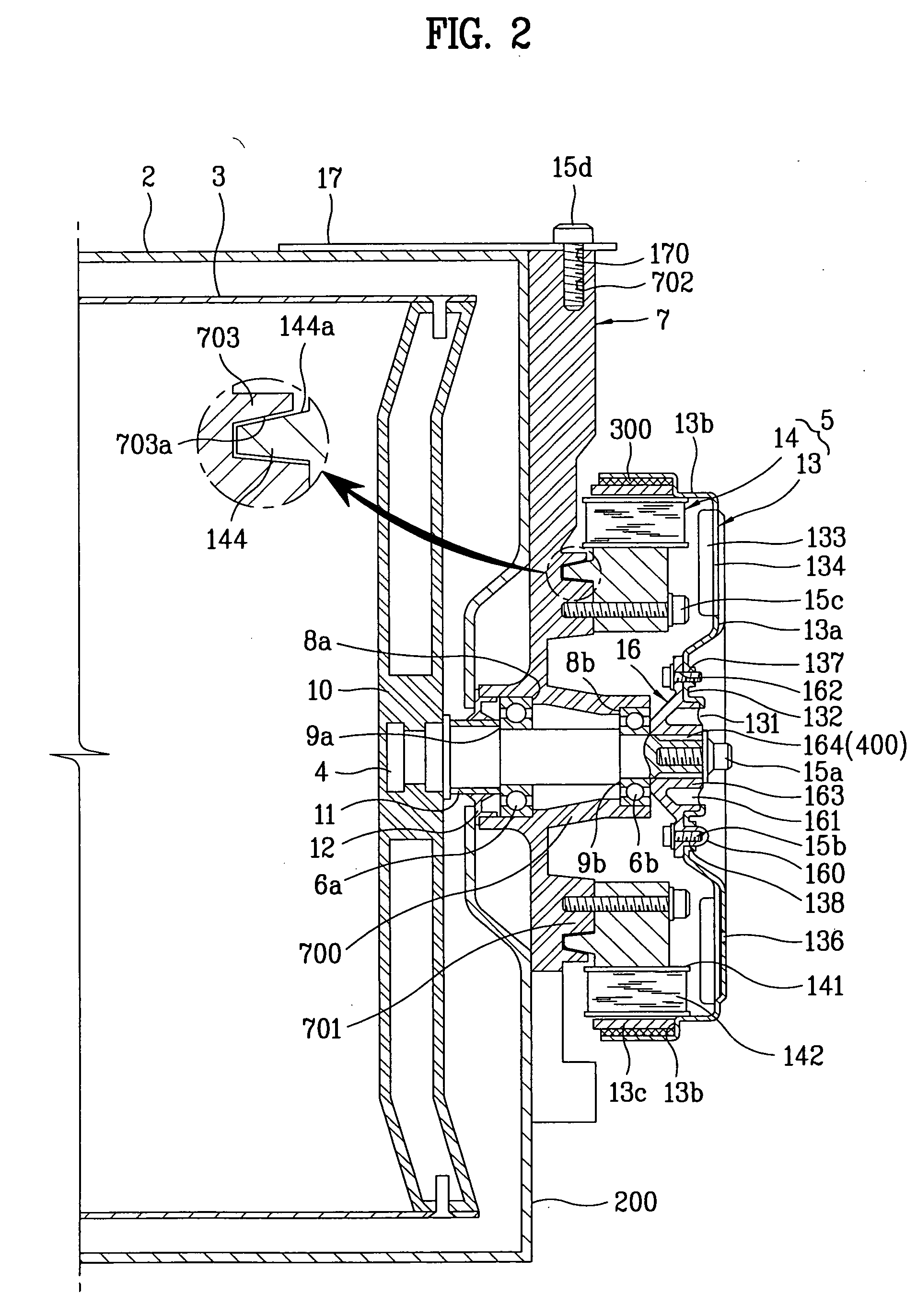
[0062] Now, the present invention will be described in detail with reference to FIGS. 2 to 7.

[0063]FIG. 2 is a longitudinal sectional view illustrating important parts of a drum type washing machine according to a first embodiment of the present invention, and FIG. 3 is a right side view of FIG. 2, in which the illustration of a motor is omitted.

[0064]FIG. 4 is a partially cut-away perspective view illustrating a rotor shown in FIG. 2, FIG. 5 is a perspective view illustrating a stator shown in FIG. 2, FIG. 6 is a perspective view illustrating a connector shown in FIG. 2, and FIG. 7 is a bottom perspective view of FIG. 6.

[0065] The drum type washing machine according to the present embodiment comprises a tub 2 installed in a cabinet (not shown) and used to receive wash water therein, a drum 3 rotatably provided in the tub 2 and adapted to wash laundry received therein as it is rotated, a shaft 4 penetrated through the tub 2 and connected to the drum 3, the shaft 4 being adapted to...

second embodiment

[0120]FIG. 8 is a longitudinal sectional view schematically illustrating the configuration of a drum type washing machine using a direct connection motor according to the present embodiment, and FIG. 9 is an enlarged longitudinal sectional view of the portion “A” of FIG. 8, illustrating the configuration of a drive unit included in the drum type washing machine according to the present invention.

[0121]FIG. 10 is a perspective view illustrating the rear wall portion of the tub shown in FIG. 9, FIG. 11 is a top perspective view of the bearing housing shown in FIG. 9, FIG. 12 is a rear perspective view of the bearing housing, and FIG. 13 is a sectional view taken along the line I-I of FIG. 11.

[0122] The present embodiment has a feature in that a bearing housing 7′ is integrally formed with the tub 2, which is made of a plastic material, at the center of the rear wall portion of the tub 2. The bearing housing 7′ of the present embodiment can rotatably support the shaft 4 while allowing...

fourth embodiment

[0147] Now, a drum type washing machine according to the present invention will be described in detail with reference to FIG. 15.

[0148] The present embodiment has a feature in that a distance regulation washer is provided in addition to the configuration of the above described fourth embodiment. The distance regulation washer is interposed between the supporter and the stator and adapted to regulate a distance between the tub and the stator.

[0149] More specifically, in the present embodiment, the distance regulation washer 500 may be interposed between the supporter 27 and the stator 14 coupled to the supporter 27 and adapted to regulate a distance between the tub 2 and the stator 14. Preferably, the distance regulation washer 500 has an annular form suitable to stably separate the stator 14 from the tub 2. The distance regulation washer 500 may be formed, in a circumferential direction thereof, with a plurality of coupling holes. Accordingly, the distance regulation washer 500 per...


PUM


Abstract

A washing machine, more particularly, an improvement in the structure of a drive unit included in a drum type washing machine is disclosed. The washing machine includes a tub for receiving wash water therein, a drum rotatably disposed in the tub and adapted to wash laundry received therein, a shaft penetrated through the tub to thereby be connected to the drum, the shaft being adapted to transmit a drive force of a motor to the drum, a stator coupled fixedly to a rear wall portion of the tub, and a rotor including at least one magnet, a back yoke defining a magnetic path, and a rotor frame rotatably disposed at the outside of the stator, the rotor frame being connected to the shaft so as to transmit a rotating force of the rotor to the shaft. The rotor frame includes a side wall portion and a rear wall portion, and is made of an aluminum material.

Description

[0001] This application claims the benefit of the Korean Patent Application Nos. 10-2005-0111504, 10-2005-0111505, 10-2005-0111506 and 10-2005-0111507 filed on Nov. 21, 2005 which are hereby incorporated by reference as if fully set forth herein. BACKGROUND OF THE INVENTION [0002] 1. Field of the Invention [0003] The present invention relates to a washing machine, and more particularly, to an improvement in the structure of a drive unit included in a drum type washing machine. [0004] 2. Discussion of the Related Art [0005] Generally, drum type washing machines are designed to perform a washing operation by use of a frictional force between a drum and laundry as the drum is rotated by a drive force of a motor transmitted thereto in a state wherein the laundry is received in the drum together with wash water and detergent. The above described washing operation manner has several effects of causing damage to laundry as little as possible while preventing entangling of laundry and also ...

Claims


Application Information

Patent Timeline
Patent Type & Authority Applications(United States)
IPC IPC(8): D06F23/00
CPCD06F37/304
Inventor KIM, YOUNG SOOCHOI, SOUNG BONG
Owner LG ELECTRONICS INC
Why Eureka
Try Eureka