
Fault tolerant aircraft flight control system and aircraft preferably having such an aircraft flight control system

a flight control system and fault-tolerant technology, applied in the field of aircraft flight control systems and aircraft, can solve the problems of high cost, high cost, and unsatisfactory flight control system, and the traditional triplex architecture generally has a substantial weight, and the effect of reducing the number of aircraft in the flight control system

Pending Publication Date: 2022-08-25
LILIUM EAIRCRAFT GMBH
View PDF0 Cites 0 Cited by
  • Summary
  • Abstract
  • Description
  • Claims
  • Application Information

AI Technical Summary

Benefits of technology

The invention is about a new flight control computer system for aircraft that is more resilient against failures. It achieves this by using multiple communication busses and bus nodes that are associated with each other in an intelligent manner, making the system more fail-tolerant. The flight control computers are connected to the communication busses through independent bus sub-systems, which substantially contributes to the desired resiliency against failures. The system also includes a triplex architecture that provides a system tolerant to any single failure, while keeping required availability and redundancy requirements. The invention combines the benefits of a triplex architecture with the benefits of a dual CAN network, which is lighter and simpler, but more robust against failures.

Problems solved by technology

However, traditional triplex architectures generally have a substantial weight, because of a higher number of busses, connectors and the necessary physical path segregation.
State of the art technology solutions for bus communication generally have the following disadvantages: rather slow communication (e.g. ARINC-429), need for a critical bus controller or router (e.g. MIL-STD-1553, AFDX), high costs (e.g. MIL-STD-1554, AFDX), proprietary single supplier (monopoly and therewith resulting high costs and unwanted dependency from a single source) or use of complex technology (e.g. TTE, TTP, .
. . ), are rather heavy because of many wires (e.g. RS-422 full duplex) and have limitations in the network configuration, e.g. not allowing N-to-N communication.
Based on conventional approaches, the use of other communication busses and in particular the use of CAN bus architecture for fly-by-wire flight control systems is limited to unmanned operations.

Method used


Image

  • Fault tolerant aircraft flight control system and aircraft preferably having such an aircraft flight control system
  • Fault tolerant aircraft flight control system and aircraft preferably having such an aircraft flight control system
  • Fault tolerant aircraft flight control system and aircraft preferably having such an aircraft flight control system

Examples


Embodiment Construction

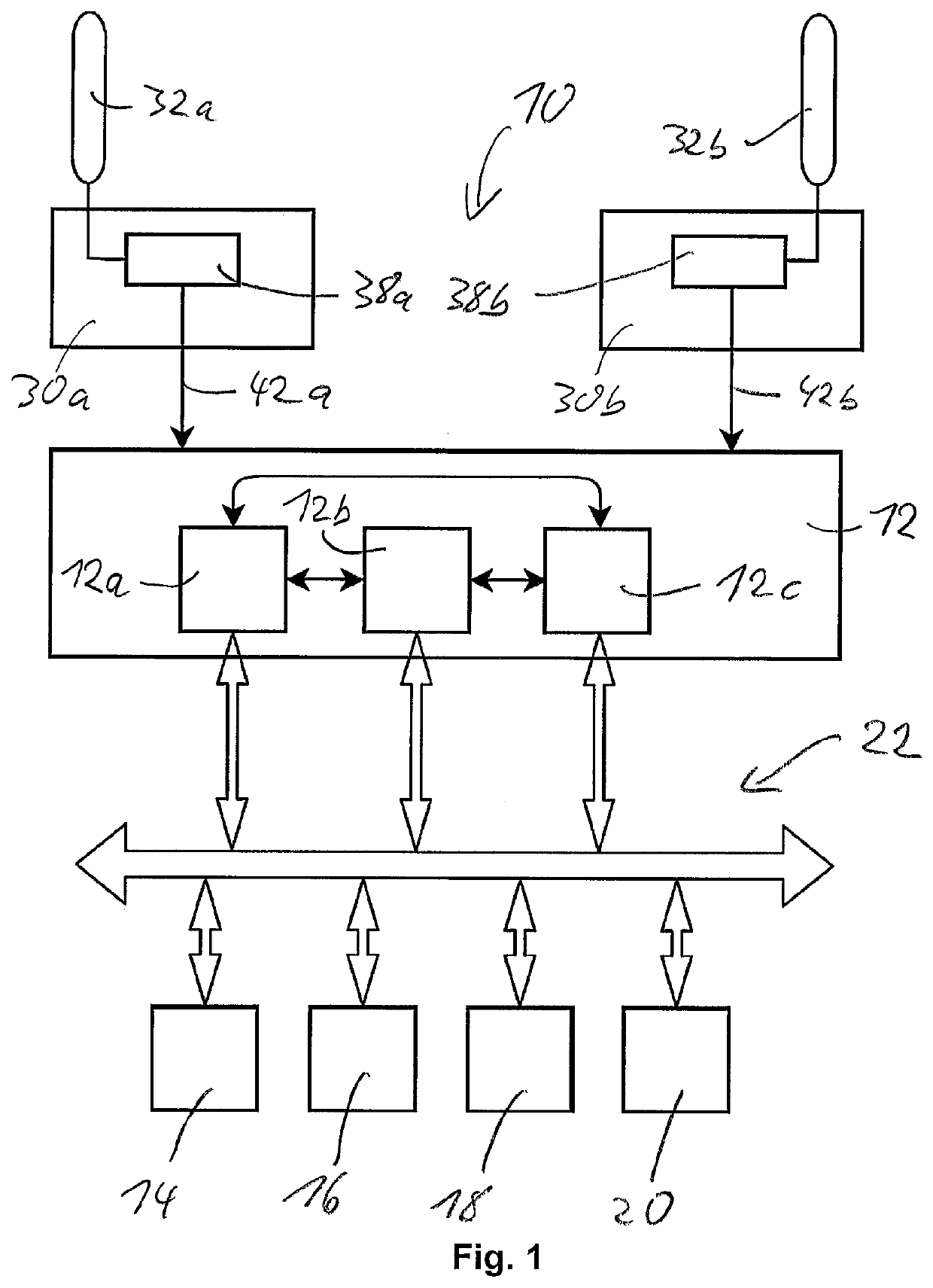
[0085]FIG. 1 shows and illustrates schematically a non-limiting example for a flight control system 10. The flight control system has a flight control computer system 12, which may be realized according to conventional concepts, in particular concepts, which provide for redundancy. An example is an as such conventional triplex architecture having three redundant flight control computers 12a, 12b and 12c, which may be connected redundantly with the pilot user interface on the one hand and elements and devices of the aircraft to be controlled based on the pilot's commands on the other hand. As examples for conventional redundancy concepts, it may be referred to U.S. Pat. No. 7,337,044 B2, U.S. Pat. No. 8,935,015 B2 and U.S. Pat. No. 8,818,575 B2.

[0086]In FIG. 1, various components of the aircraft are represented schematically by elements 14 to 20, which may represent various aircraft devices, such as sensors, actuators (such as actuators for controllably moving flight control surfaces...


PUM


Abstract

A flight control system for an aircraft comprises a flight control computer system connected via a bus system with a plurality of bus nodes, which each are configured to at least one of controlling an associated aircraft device based on command messages received from the flight control computer system via the bus system and sending information messages to the flight control computer system via the bus system. The bus system is a redundant bus system comprising plural independent bus sub-systems, wherein each bus node is configured to communicate with the flight control computer system via two different bus sub-systems, wherein each bus node further is configured to communicate with the flight control computer system on basis of an associated predetermined bus communication protocol via a first bus sub-system and on basis of an associated predetermined bus communication protocol via a second bus sub-system.

Description

TECHNICAL FIELD[0001]The present invention generally relates to a flight control system for an aircraft, and an aircraft, that may have such a flight control system. In particular, the invention relates to an aircraft to the canard type having multiple lift / thrust units distributed along the front or canard wings and along the aft or main wings.BACKGROUND[0002]Aircrafts maybe generally classified into fixed wing and rotating wing types. Fixed wing aircrafts typically include a plurality of flight control surfaces that, when controllably positioned, guide the movement of the aircraft from one destination to another destination. The number and type of flight control surfaces included in an aircraft may vary. Primary flight control surfaces are typically those that are used for control the aircraft movement with respect to the pitch, yaw and roll axes. Secondary flight control surface are typically those that are used to influence the lift or drag (or both) of the aircraft. Typical pri...

Claims


Application Information

Patent Timeline
Patent Type & Authority Applications(United States)
IPC IPC(8): G05D1/10B64C9/04B64C13/50B64C13/26B64D27/02B64D31/02B64C39/12H04L12/40H04L69/18
CPCG05D1/102B64C9/04B64C13/50B64C13/26B64D27/02B64D31/02B64C39/12H04L12/40032H04L69/18B64C29/00B64C19/00B64D31/00B64C13/00G05D1/0077B64C13/503B64C13/505B64D31/14B64C9/08B64C29/0033B64C15/12H04L2012/40215H04L2012/4028H04L12/40006B64D2221/00B64D31/16B64D27/31B64D27/34H04L12/40189
Inventor TELES FERREIRA, JOÃO FILIPERIBAS, GABRIEL OLIVEIRA
Owner LILIUM EAIRCRAFT GMBH
Learn More