Knitting method for wide rib texture by plating

Inactive Publication Date: 2007-07-26
SHIMA SEIKI MFG LTD
View PDF2 Cites 1 Cited by
  • Summary
  • Abstract
  • Description
  • Claims
  • Application Information

AI Technical Summary

Benefits of technology

[0010] In the knitting method of the present invention, the tubular knitted fabric including the wide rib structure formed by the plating is knitted using the flat knitting machine, while the crossing of the knitting yarns used for the plating is located in the crossover portion of the wide rib. From the nature of this knitted fabric, the front stitch on the edge and the back stitch on the edge are curled to each other to put the blur in the shade. Hence, the blur can be made less noticeable.
[0011] When the front stitch on the edge and the back stitch on the edge are formed at the end on the side on which the crossing occurs using knitting needles spaced one to three needles apart in the knitting width direction, a crossover yarn extending between the ribs is elongated. This can put the blur in the shade more effectively and thus can be even less noticeable.

Problems solved by technology

However, this conventional plating involves the following problems when a tubular knitted fabric, such as knitwear of a wide rib structure whose front and back knitted fabrics are joined to each other at lateral sides thereof and in which a number of front stitches and back stitches come out alternately by the plating, is knitted using a flat knitting machine.
When the next stitch is formed in the state of the front yarn and the back yarn being reversed in position for a moment by the crossing, the yarn which really should not come out comes to the front side, causing blur (color mixing) of the knitted fabric at lateral ends thereof and thus reducing the commercial value of the knitwear.
In the plating using the flat knitting machine, such a crossing of the knitting yarns cannot be avoided.

Method used


Image

  • Knitting method for wide rib texture by plating
  • Knitting method for wide rib texture by plating
  • Knitting method for wide rib texture by plating

Examples


Embodiment Construction

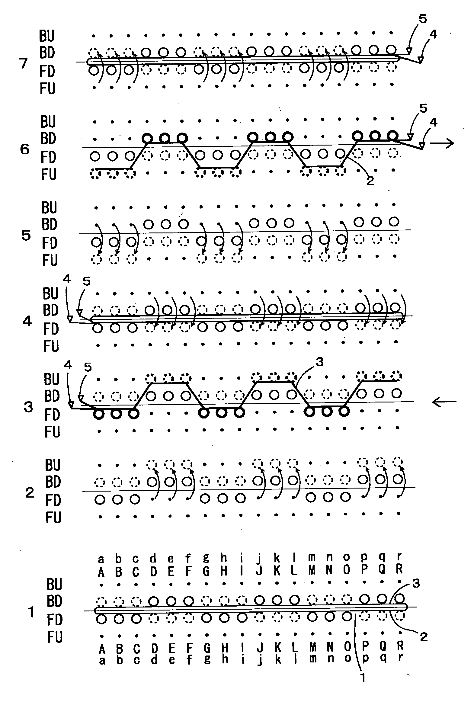
[0012] Next, an embodiment of the present invention is described with reference to accompanying drawings.

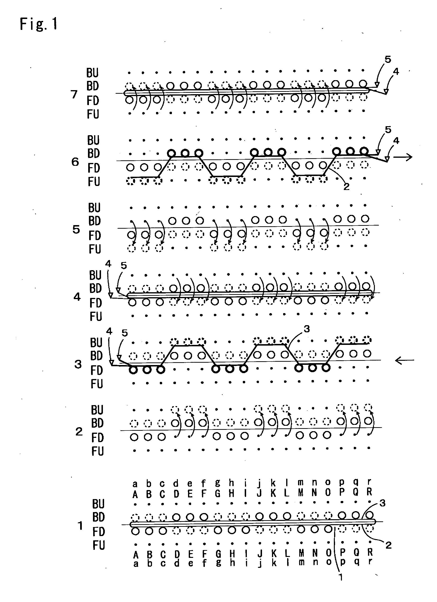
[0013]FIG. 1 is a knitting process drawing of a wide rib knitted fabric 1 knitted by the plating in the illustrated embodiment. The wide rib is a 3×3 rib structure comprising three front stitches (solid line) and three back stitches (broken line). In the tubular knitted fabric, the front knitted fabric 2 and the back knitted fabric 3 are joined to each other at ends thereof.

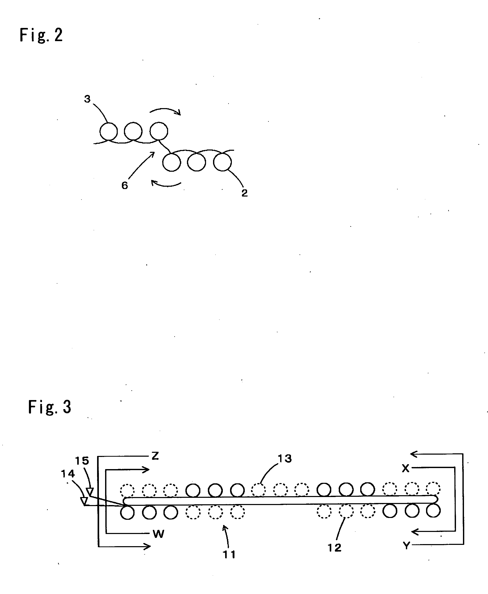
[0014] In the illustrated embodiment, a four-bed flat knitting machine comprising a pair of front lower needle bed FD and back lower needle bed BD arranged in front and back and a pair of front upper needle bed FU and back upper needle bed BU arranged over them is used. In the knitting, the knitting needles a-r of the upper needle beds and the knitting needles A-R of the lower needle beds are used. In the knitting of the wide rib knitted fabric 1, the front knitted fabric 2 is assigned to the front lower nee...


PUM


Abstract

The present invention provides a knitting method that when a knitted fabric having a wide rib structure formed by the plating using a front knitting yarn and a back knitting yarn different in color from each other, in particular, using a flat knitting machine, can make less noticeable a blur of the knitted fabric at an end of the knitting width to thereby produce a good looking wide rib structure. Using a flat knitting machine, a front stitch of the rib structure of one knitted fabric at an end of a knitted width thereof on the side on which the crossing of the knitting yarns used for the plating occurs is formed as a front stitch on the edge, and a back stitch of the rib structure of the other knitted fabric on that side is formed as a back stitch on the edge. After the front stitch of the rib structure of the one knitted fabric is knitted, the back stitch of the rib structure of the other knitted fabric is knitted changing a knitting direction, whereby the crossing is located in a crossover portion of the wide rib and thereby the blur of the knitting yarns is made less noticeable.

Description

TECHNICAL FIELD [0001] The present invention relates to a knitting method for knitting a wide rib structure by plating using a flat knitting machine. BACKGROUND ART [0002] The plating is a knitting technique of knitting a knitted fabric in such a manner that a front yarn and a back yarn are both fed to knitting needles so that the front yarn can come to the front side of the front stitch formed and also the back yarn can come to the back side (the reverse side) of the front stitch so that the back yarn can be enfolded by the front yarn. The back yarn comes to the front side of back stitch formed and also the front yarn is hidden behind the back side (the reverse side) thereof. Due to this, the plating requires that the back yarn be located nearer to a hook side than the front yarn. For this, the plating is carried out, for example, by using both a front-yarn yarn feeder and a back-yarn yarn feeder and driving them in such a timed sequence that the front-yarn yarn feeder is driven ah...

Claims


Application Information

Patent Timeline
IPC IPC(8): D04B7/04D04B1/22D04B1/00D04B7/00D04B7/26D04B7/32
CPCD04B1/126D10B2403/0114D04B1/246D04B7/26D04B7/32D04B1/00
Inventor SHIMASAKI, YOSHINORI
Owner SHIMA SEIKI MFG LTD
Why Eureka
Try Eureka