Lighting fixture

a technology of light fixture and heat sink, which is applied in the direction of lighting support devices, lighting applications, applications, etc., can solve the problems of reducing task performance, inconvenient construction of valances, and insufficient illumination,

Inactive Publication Date: 2007-08-02
GRIGORIK VLADIMIR
View PDF3 Cites 22 Cited by
  • Summary
  • Abstract
  • Description
  • Claims
  • Application Information

AI Technical Summary

Benefits of technology

[0019] Other advantages, features and characteristics of the present invention, as well as methods of operation and functions of the related elements of the structure, and the combination of parts and economies of manufacture, will become more apparent upon consideration of the following detailed description and the appended claims with reference to the accompanying drawings, the latter of which is briefly described herein below.

Problems solved by technology

In such installations, the eye level of persons in a typical viewing area must be considered, as it is undesirable to view the light source directly.
Further, newly developed high brightness light emitting diodes can generate twelve to fifteen candela as a point light source under normal lighting conditions, which is intensely bright and therefore undesirable to view directly.
Such glare typically reduces task performance, which is undesirable for a work area.
Such construction of a valance is typically time consuming, inconvenient, and adds additional cost to the overall structure.
Further, proper thermal management is critical in the design of lighting fixtures, especially those that have light emitting diodes as a light source, since temperature significantly affects light emitting diode performance and reliability.
Light emitting diodes generate heat due to electrical power dissipation.
If the junction temperature of the light emitting diode is higher than its rated junction temperature, the output of the light emitting diode will be reduced, the dominant wavelength or perceived colour of the light emitting diode will change, and the light emitting diode may be driven to wear out prematurely or even to catastrophic failure.
Accordingly, the power density becomes unacceptably high and the Metal-Core-Printed-Circuit-Boards or other type of heat spreader tends to become unacceptably hot.
Unfortunately, it is generally inconvenient, costly, complicated and difficult to mount a heatsink on a linear light emitting diode light engine.
It can therefore be readily seen that, in the prior art, in order to provide a linear light emitting diode light engine with a heatsink and also install it with a valance is generally inconvenient, costly, complicated and difficult, and time consuming.
Further complicating matters, it is usually necessary that the entire lighting arrangement be aesthetically attractive, which is difficult to accomplish using a conventional heatsink, especially in combination with a valance.

Method used


Image

  • Lighting fixture
  • Lighting fixture
  • Lighting fixture

Examples


Embodiment Construction

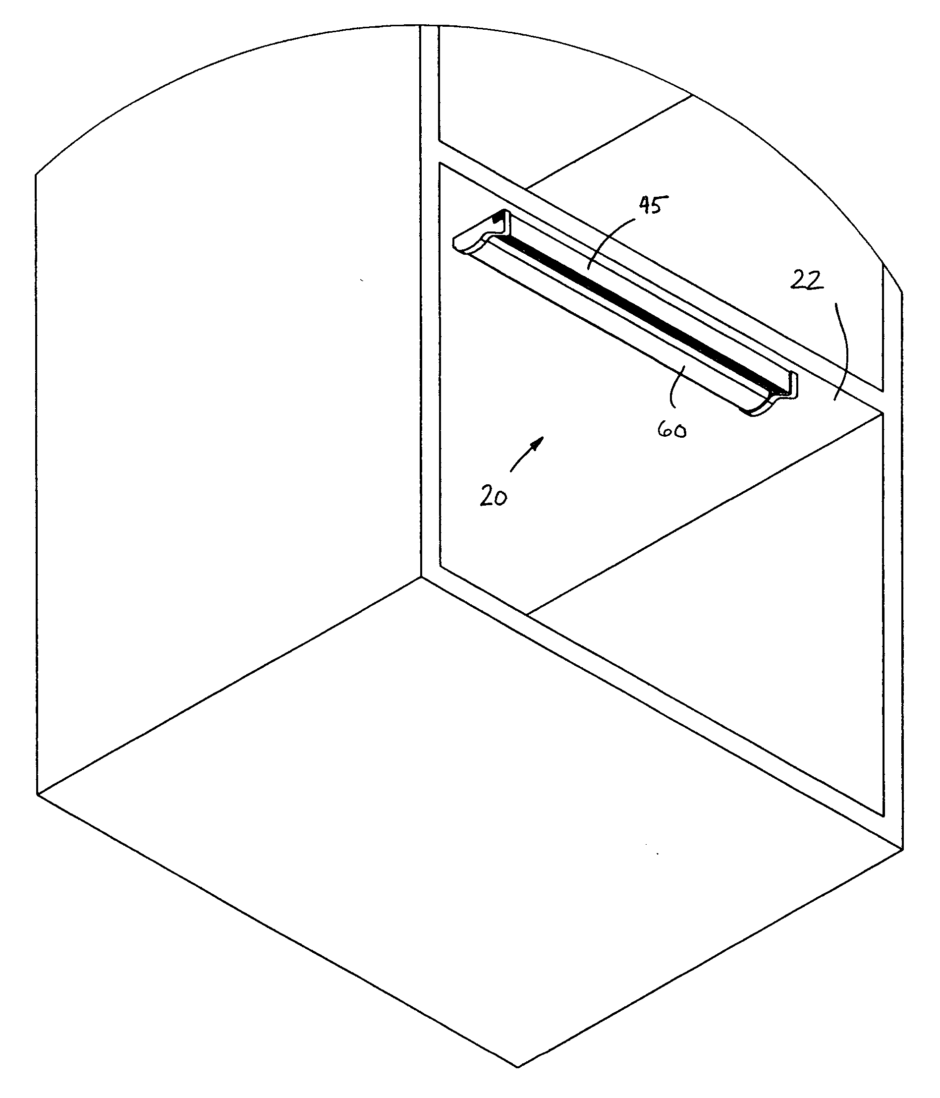
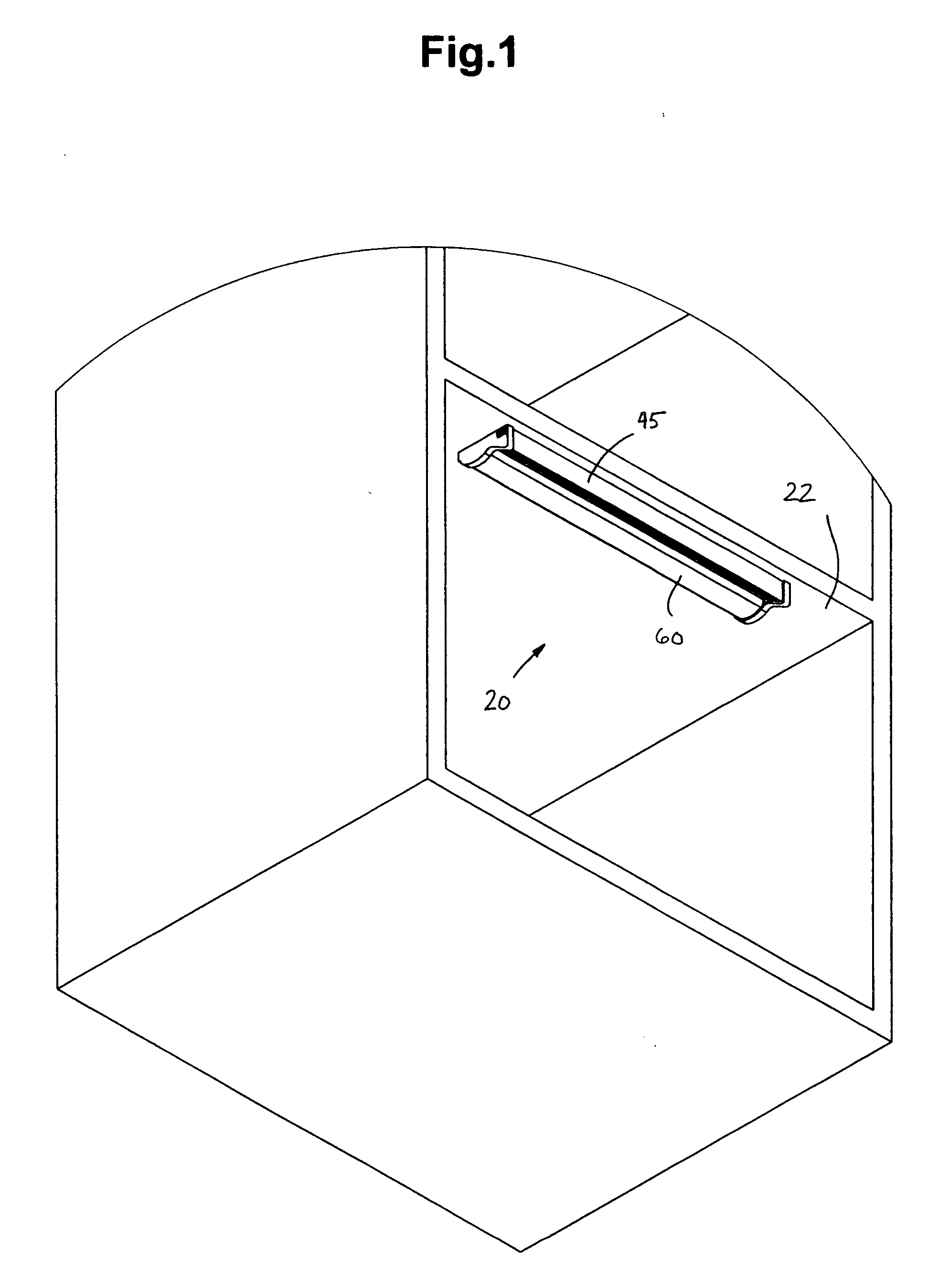
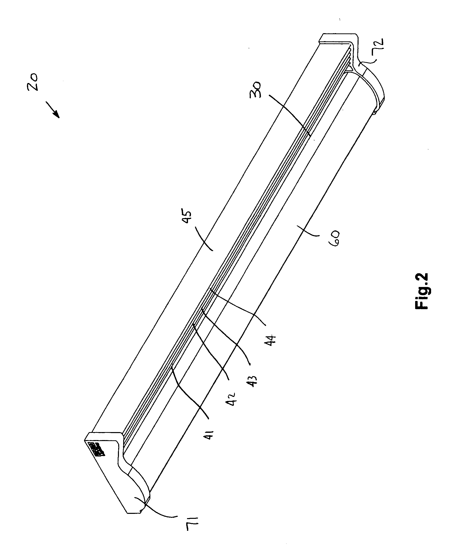
[0053] Referring to FIGS. 1 through 32 of the drawings, it will be noted that FIGS. 1 through 12 illustrate a first preferred embodiment of the lighting fixture of the present invention, FIGS. 13 through 16 illustrate a second preferred embodiment of the lighting fixture of the present invention, FIGS. 17 through 19 illustrate a third preferred embodiment of the lighting fixture of the present invention, FIG. 20 illustrates a fourth preferred embodiment of the lighting fixture of the present invention, FIG. 21 illustrates a fifth preferred embodiment of the lighting fixture of the present invention, FIG. 22 illustrates a sixth preferred embodiment of the lighting fixture of the present invention, FIG. 23 illustrates a seventh preferred embodiment of the lighting fixture of the present invention, FIG. 24 illustrates an eighth preferred embodiment of the lighting fixture of the present invention, FIG. 25 illustrates a ninth preferred embodiment of the lighting fixture of the present i...


PUM

PropertyMeasurementUnit
heat conductiveaaaaaaaaaa
luminous intensity distributionaaaaaaaaaa
luminanceaaaaaaaaaa

Abstract

A lighting fixture comprises a base portion and at least one valance portion oriented so as to project outwardly from the base portion. The at least one valance portion is connected in heat conductive relation to the base portion, to thereby act as a heatsink. There is at least one light source mounted on one of the base portion and the at least one valance portion, such that the at least one valance portion is substantially adjacent the at least one light source, to thereby obstruct the direct viewing of the at least one light source from beyond the at least one valance portion when the lighting fixture is installed on a supporting structure.

Description

FIELD OF THE INVENTION [0001] The present invention relates to lighting fixtures, and more particularly to heatsinks and valances for lighting fixtures. BACKGROUND OF THE INVENTION [0002] Lighting fixtures, also known as luminaries, are defined as a complete lighting unit consisting of a light source together with the parts designed to distribute the light, to position and protect the light source, and to connect the light source to a power supply. It is very important, and in many cases necessary, to have a luminaire with the proper luminous intensity distribution for successful lighting. Luminaries can produce patterns of light that are interesting and important with respect to the appearance of the space being lit. The requirements for contrast and luminance determine the luminous intensity distribution and the placement of luminaries. [0003] In many instances, both direct and indirect lighting are commonly needed to properly illuminate either a display area or a work area. It is...

Claims


Application Information

Patent Timeline
Patent Type & Authority Applications(United States)
IPC IPC(8): F21V19/00
CPCF21S8/033F21V3/02F21V7/0008F21V11/00F21W2131/402F21W2131/301F21V29/75F21V29/763F21V29/767F21S4/20F21Y2103/10F21Y2115/10
Inventor GRIGORIK, VLADIMIR
Owner GRIGORIK VLADIMIR
Why Eureka
Try Eureka