Multicarrier signal transmission apparatus and multicarrier signal transmission method

a multi-carrier signal and transmission apparatus technology, applied in the direction of digital transmission, electrical apparatus, transmission, etc., can solve the problems of adjacent channel leakage power ratio (aclr) degradation, achieve the effect of reducing the papr, avoiding unnecessarily large peak suppression, and suppressing the peak par

Inactive Publication Date: 2007-08-02
FUJITSU LTD
View PDF6 Cites 4 Cited by
  • Summary
  • Abstract
  • Description
  • Claims
  • Application Information

AI Technical Summary

Benefits of technology

[0027] Therefore, finally, the peak suppression using the above window function is used to suppress the peak part of the filtered signal and thereby reduce the PAPR.
[0028] In this peak suppression using a window function, for example, the window function is generated based on a cos window function, cos2 window function, cos3 window function, cos4 window function, Hanning window function, Hamming window function, Kaiser window function, Blackman-Harris window function, etc. and the signal values of the filtered signal are attenuated in accordance with the value taken by the window function. The above illustra...

Problems solved by technology

On the other hand, the hard clip type peak suppression method causes a high frequency component in the multicarrier signa...

Method used


Image

  • Multicarrier signal transmission apparatus and multicarrier signal transmission method
  • Multicarrier signal transmission apparatus and multicarrier signal transmission method
  • Multicarrier signal transmission apparatus and multicarrier signal transmission method

Examples


first embodiment

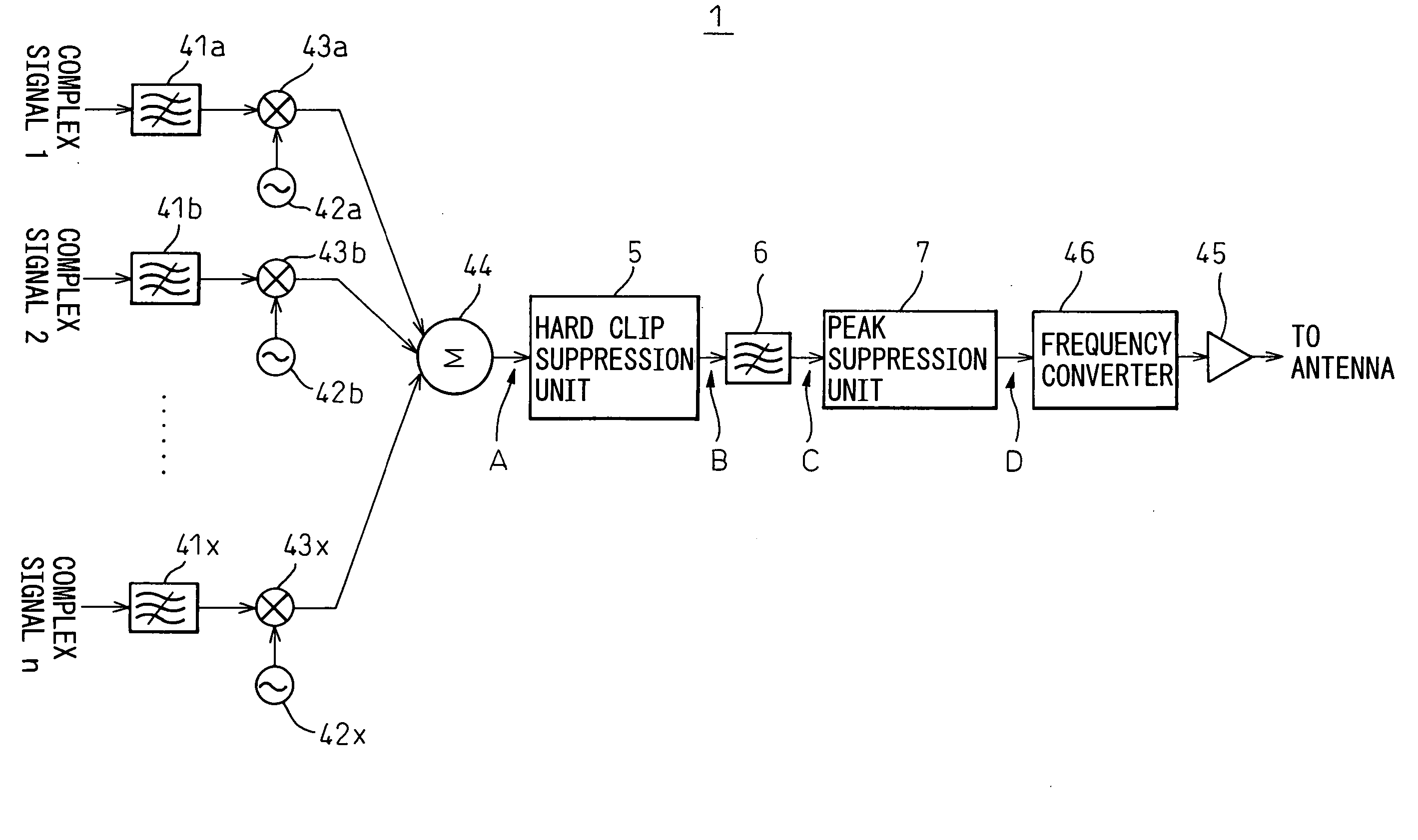
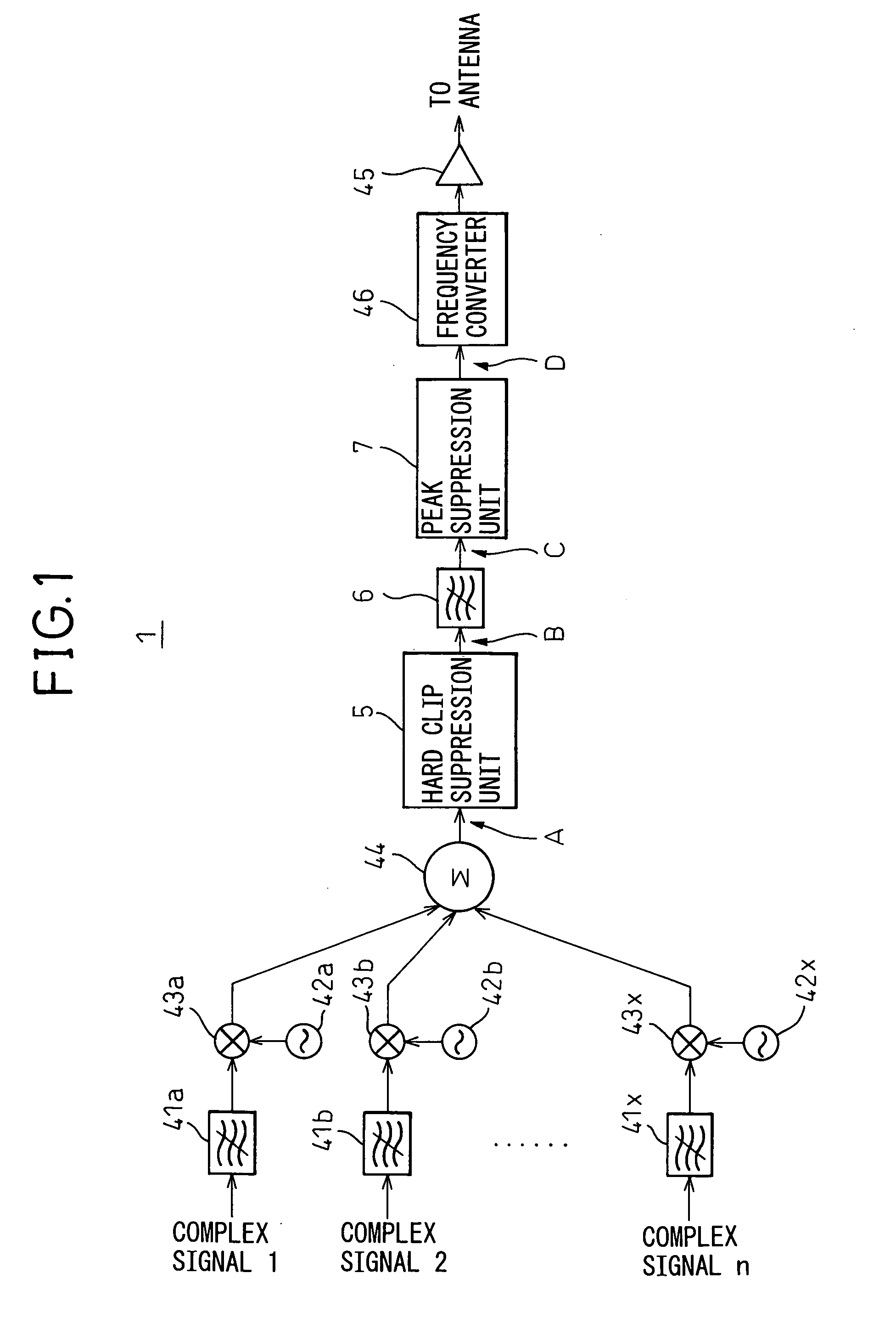
[0059]FIG. 1 is a schematic view of the configuration of a multicarrier signal transmission apparatus according to the present invention. As illustrated, the transmission apparatus 1 over-samples, then limits the bands of the plurality of digital baseband signals comprised by the complex signal 1, complex signal 2 . . . complex signal n by band-limiting filters 41a, 41b . . . 41x, respectively.

[0060] After this, sine wave generators 42a, 42b . . . 42x generate different frequency fa, fb . . . fx complex sine waves ejωt (ω=2πfa, 2πfb . . . 2πfx), while complex multipliers 43a, 43b . . . 43x multiply the same with the complex signal 1, complex signal 2 . . . complex signal n respectively to shift them to the frequencies.

[0061] Further, the complex signal 1 to complex signal n shifted to the frequencies and band limited are combined by a multicarrier combiner 44 into a multicarrier signal.

[0062] The combined multicarrier signal is successively input to the later explained hard clip s...

second embodiment

[0136]FIG. 16 is a schematic view of the configuration of a multicarrier signal transmission apparatus according to the present invention. This embodiment performs the peak suppression by hard clipping, a low pass filter, and window function and the peak suppression before multicarrier combination together.

[0137] That is, the transmission apparatus 1 according to the present embodiment is provided with, in addition to the above explained hard clip suppression unit 5, low pass filter 6, and peak suppressing means 6, a precombination suppression coefficient calculator 61 for simulating a multicarrier signal occurring when limiting the bands of, then combining the digital signals comprised of the complex signal 1 to complex signal n based on the same so as to determine the peak parks and computing the suppression coefficients (attenuation coefficients) to be applied to the segments of the complex signal 1 to complex signal n corresponding to the determined peak parts, multipliers 62a, ...


PUM


Abstract

A multicarrier signal transmission apparatus provided with a hard clip suppression unit for hard clipping a peak part of a multicarrier signal, a low pass filter for filtering the signal hard clipped by the hard clip suppression unit, and a peak suppression unit for suppressing the peak part of the signal after filtering by the low pass filter, the peak suppression unit provided with a peak detection unit for detecting a peak part of the filtered signal, a window function generation unit for generating a window function of an amplitude in accordance with a peak level of the peak part, and a peak suppressor for attenuating the peak part in accordance with the value of the window function.

Description

CROSS REFERENCE TO RELATED APPLICATION [0001] This application is based upon and claims the benefit of priority from the prior Japanese Patent Application No. 2006-9938, filed on Jan. 18, 2006, the entire contents of which are incorporated herein by reference. BACKGROUND OF THE INVENTION [0002] 1. Field of the Invention [0003] The present invention relates to a transmission apparatus for a multicarrier signal combining a plurality of modulated signals, more particularly relates to a transmission apparatus for suppressing the peak power of a multicarrier signal to improve a peak-to-average power ratio (PAPR). [0004] 2. Description of the Related Art [0005] Digital wireless communication systems use multicarrier modulation schemes for combining a plurality of band-limited carrier signals and transmitting them by a high frequency carrier. FIG. 17 is a schematic view of the configuration of a conventional digital wireless transmission apparatus for multicarrier modulation. [0006] As ill...

Claims


Application Information

Patent Timeline
IPC IPC(8): H04B1/04H04B1/02
CPCH04L27/2623
Inventor HAMADA, HAJIMEKUBO, TOKURONAGATANI, KAZUOISHIKAWA, HIROYOSHIFUDABA, NOBUKAZU
Owner FUJITSU LTD
Why Eureka
Try Eureka