Optical communication system, optical transmitter, optical receiver, and optical transponder

Inactive Publication Date: 2012-11-22
HITACHI LTD
View PDF4 Cites 20 Cited by
  • Summary
  • Abstract
  • Description
  • Claims
  • Application Information

AI Technical Summary

Benefits of technology

[0028]The present invention can provide an optical communication system, an optical transmitter, an optical receiver, and an optical transponder that can reduce the PAPR where the photoelectric power is high within the transmission line in an optical OFDM communication system, thus enabling sensitivity degradation to be reduced. Furthermore, the invention can provide an optical communication system, an optical transmitter,

Problems solved by technology

However, such an approach in which an increase in communication capacity is achieved by an increase in modulation speed typically has the following problems.
That is, increasing the modulation speed may cause a problem in that the achievable transmission distance, which is limited by the wavelength dispersion of the optical fiber, is reduced.
In addition, increasing the modulation speed may cause another problem in that the achievable transmission distance limited by the polarization mode dispersion of the optical fiber is also reduced.
In the case of the next generation systems, i.e., 100 Gbps systems, the achievable transmission distance limited by the wavelength dispersion may be further reduced to 0.6 km, thus making it impossible to achieve a trunk-line optical communication system having a transmission distance of about 500 km.
However, such a special fiber not only is expensive but also needs a skilled design that can achieve the optimal usage of the dispersion compensation fiber (the optimal length of the dispersion compensation fiber to be used) in each site, and these problems increase the cost of the optical communication system.
Optical co

Method used


Image

  • Optical communication system, optical transmitter, optical receiver, and optical transponder
  • Optical communication system, optical transmitter, optical receiver, and optical transponder
  • Optical communication system, optical transmitter, optical receiver, and optical transponder

Examples


first embodiment

2. First Embodiment

[0071]A first embodiment will now be described with reference to FIG. 1, etc. Although it is assumed that the subcarriers are modulated using 4-QAM for exemplary purposes, the present embodiment is not limited thereto, and any subcarrier modulation method can be used. Furthermore, the number of the subcarriers is designated as N (N is an integer).

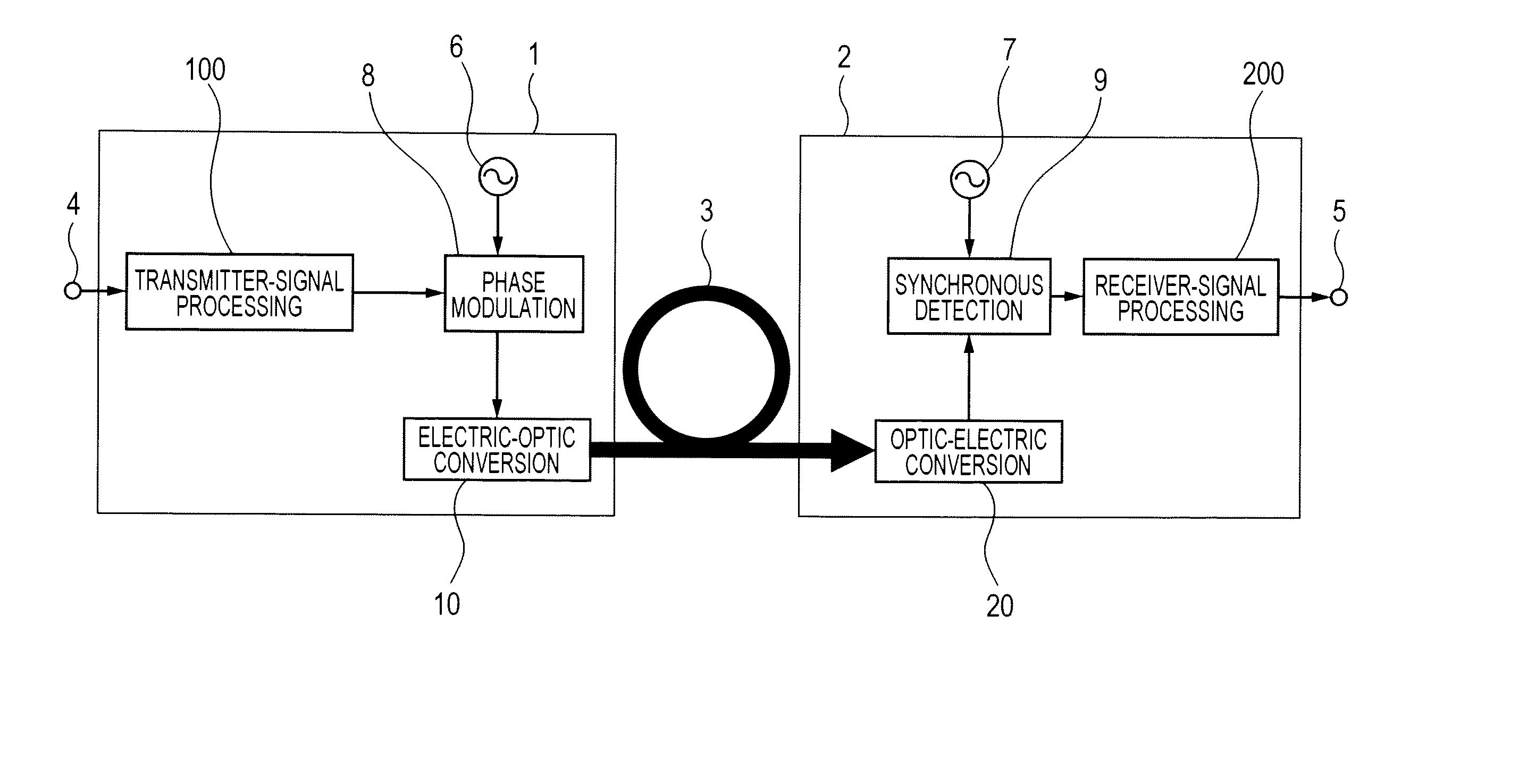
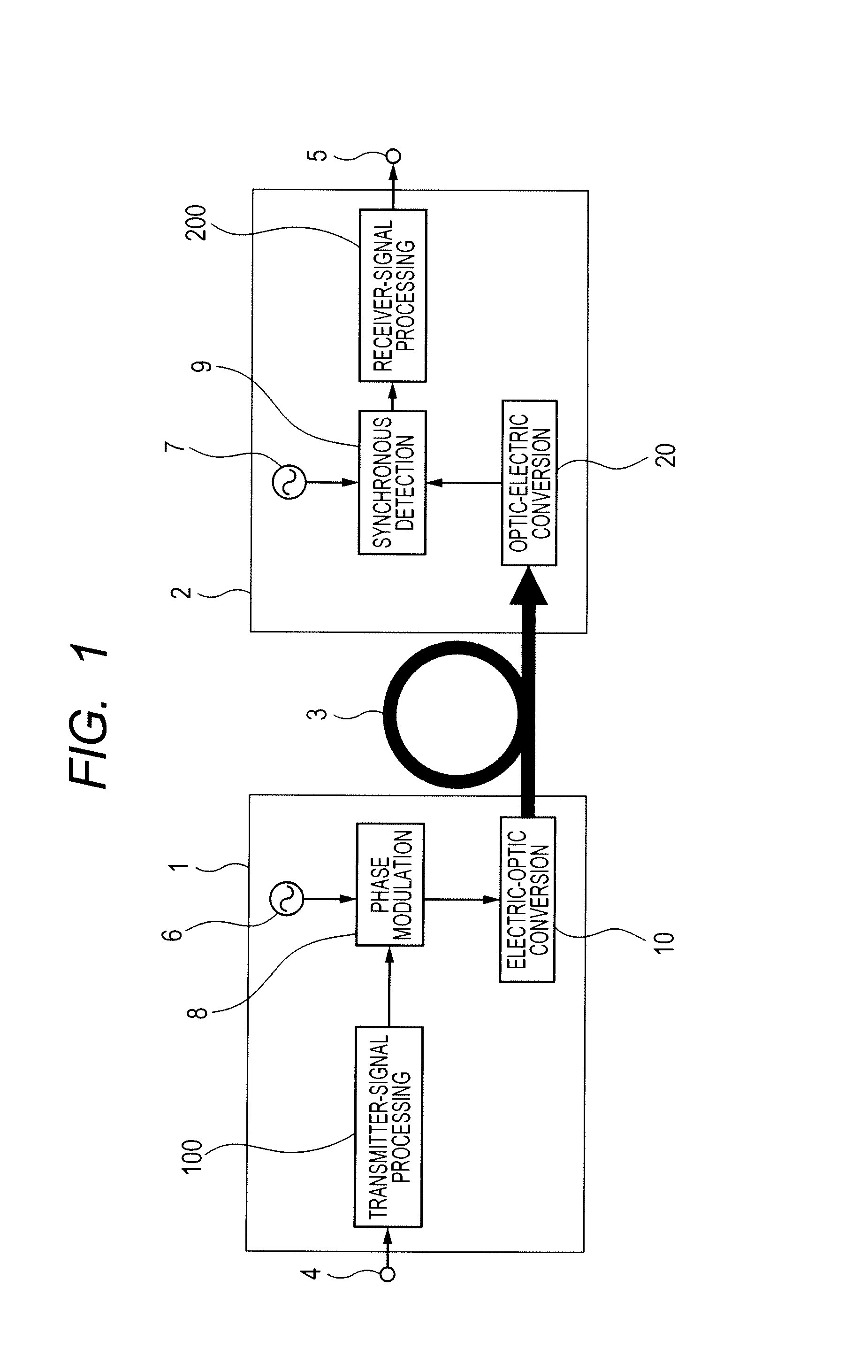
[0072]FIG. 1 shows the configuration diagram of an optical OFDM communication system.

[0073]The optical OFDM communication system includes, e.g., a transmitter (optical transmitter) 1, an optical fiber 3, and a receiver (optical receiver) 2. The transmitter 1 includes, e.g., a transmitter-signal processing unit 100, an RF oscillator 6, and an electro-optic converting unit10. The transmitter 1 may also have an input terminal 4. The receiver 2 includes an opto-electric converting unit 20 and a receiver-signal processing unit 200. The receiver 2 may also have an output terminal 8. The transmitter 1 and the receiver 2 are conn...

second embodiment

3. Second Embodiment

[0085]A second embodiment will now be described with reference to FIG. 8, etc. FIG. 8 shows a system configuration diagram according to the second embodiment. It differs from the first embodiment in that a narrow-band optical filter 14 is installed at the optical output of the electro-optic converting unit 10 in the transmitter 1-4. The narrow-band optical filter blocks a sideband wave of the optical signal output from the electro-optic converting unit 10, thus generating an optical SSB (Single Side Band) signal. Optical SSB signals are known to generate no waveform distortions due to the wavelength dispersion property of optical fibers, and are therefore suitable for long-distance communication systems.

[0086]The electro-optic converting unit 10 in the second embodiment may be a unit 10-2 shown in FIG. 6 or a unit 10-3 shown in FIG. 7, while the opto-electric converting unit 20 may be a unit 20-1 shown FIG. 5.

[0087]As another means for generating the optical SSB ...

third embodiment

4. Third Embodiment

[0091]A third embodiment will now be described with reference to FIG. 13. FIG. 13 is an overall configuration diagram of a communication system according to the third embodiment.

[0092]A receiver 2-3 according to the third embodiment includes e.g., an opto-electric converting unit 20-2, an RF oscillator 7-1, a synchronous detecting unit 9, a receiver-signal processing unit 200, a local oscillator semiconductor laser 50, and an optical combining unit 60. An optical signal transmitted from a transmitter 1 through an optical fiber 3 enters the receiver 2-3. This optical signal is combined with light output from the local oscillator semiconductor laser 50 installed in the receiver 2-3, and is received by the opto-electric converting unit 20-2 using the so-called coherent receiving method so as to be converted into an electric signal. This electric signal is synchronously detected by the synchronous detecting unit 9 using a sinusoidal wave output from the RF oscillator ...


PUM


Abstract

A sinusoidal wave output from an RF oscillator provided in a transmitter is phase-modulated using a baseband OFDM signal output from a transmitter-signal processing unit 100, and this phase-modulated sinusoidal wave is used to modulate an optical wave. Using this light as signal light to achieve optical communication enables a low PAPR value such as 6 dB or less to be achieved where the photoelectric power is high in an optical fiber, thus enabling the above described problems to be solved. This signal light travels through an optical fiber serving as the transmission line and is converted by a receiver into an electric signal. The electric signal is synchronously detected using a sinusoidal wave output from an RF oscillator oscillating at the same frequency as the above RF oscillator provided in the transmitter. Ordinary OFDM signal processing for reception is performed.

Description

TECHNICAL FIELD[0001]The present invention relates to an optical communication system, an optical transmitter, an optical receiver, and an optical transponder, and more particularly to an optical OFDM communication system and a multicarrier optical communication system. More specifically, the invention relates to an optical communication system, an optical transmitter, an optical receiver, and an optical transponder that reduce the PAPR (Peak-to-Average Power Ratio) in an optical OFDM (Orthogonal Frequency Division Multiplexing) communication system.BACKGROUND ART[0002]Optical communication systems put into practical use so far use binary modulation and demodulation technologies based on optical intensity. More specifically, the transmitting side converts digital information, i.e., “ONEs” and “ZEROs”, into ONs and OFFs in optical intensity and transmits them into an optical fiber, and the receiving side receives the light propagated through the optical fiber and recovers the origina...

Claims


Application Information

Patent Timeline
IPC IPC(8): H04J14/00H04B10/516
CPCH04J14/0298H04B10/548H04L27/2621H04L27/2614
Inventor SASAKI, SHINYA
Owner HITACHI LTD
Why Eureka
Try Eureka