Eureka AIR delivers breakthrough ideas for toughest innovation challenges, trusted by R&D personnel around the world.

Apparatus and method for controlling transmission power in a mobile communication system

a mobile communication system and apparatus technology, applied in the field of mobile communication systems, can solve the problems of cdma system needing an expensive power amplifier, the output signal of the power amplifier has a signal distortion component outside the signal frequency band, and it is difficult to design a power amplifier that meets these requirements, so as to achieve stable, feasible mobile communication system, and increase the use efficiency of the rf power amplifier

Inactive Publication Date: 2005-09-13
SAMSUNG ELECTRONICS CO LTD
View PDF9 Cites 22 Cited by
  • Summary
  • Abstract
  • Description
  • Claims
  • Application Information

AI Technical Summary

Benefits of technology

The present invention provides a method and apparatus for improving the efficiency of an RF power amplifier in a mobile communication system. This includes reducing the peak-to-average power ratio (PAPR) of the input signal to the amplifier, operating the amplifier in a linear amplification area, and maximizing suppression of spectral regrowth outside the signal frequency band. The invention also allows for simultaneous transmission of signals using multiple power amplifiers and provides a method for controlling the input signal of the amplifier using a power controller. Overall, the invention ensures a stable and feasible mobile communication system.

Problems solved by technology

If input power that ensures sufficient RF output power is outside a linear amplification area of a power amplifier, the output signal of the power amplifier has a signal distortion component outside the signal frequency band due to non-linear amplification.
It is very difficult to design a power amplifier satisfying these requirements because the former requires high input power and the latter requires low input power.
Especially, a system having a high PAPR such as CDMA (Code Division Multiple Access) must control the input power to enable the power amplifier to operate in the linear amplification area, or use an expensive power amplifier having linearity at maximum input power.
In this context, the CDMA system needs an expensive power amplifier that can accommodate a maximum input power 10 dB higher than an average input power to suppress signal distortion.
As stated above, however, such a power amplifier decreases power efficiency and increases power consumption, system size, and cost.
Moreover, the BS transmits signals with a plurality of frequency allocations (FAs) at the same time using a power amplifier for each FA, thus imposing economic constraints.
A very complicated process is involved with the distortion measurement, such as modulation and demodulation, sampling, quantization, synchronization, and comparison between input and output.
However, optimum distortion compensation cannot be achieved with this pre-distortion adjusting circuit due to its shortcomings associated with efficiency, speed, and complexity.
The decrease of the signal level at a predetermined rate or the decrease of a signal level greater than a threshold to a predetermined level results in drastic changes in the signal level and a power increase outside the signal frequency band.
Consequently, the overall system performance is deteriorated.

Method used


Image

  • Apparatus and method for controlling transmission power in a mobile communication system
  • Apparatus and method for controlling transmission power in a mobile communication system
  • Apparatus and method for controlling transmission power in a mobile communication system

Examples


first embodiment

[0044

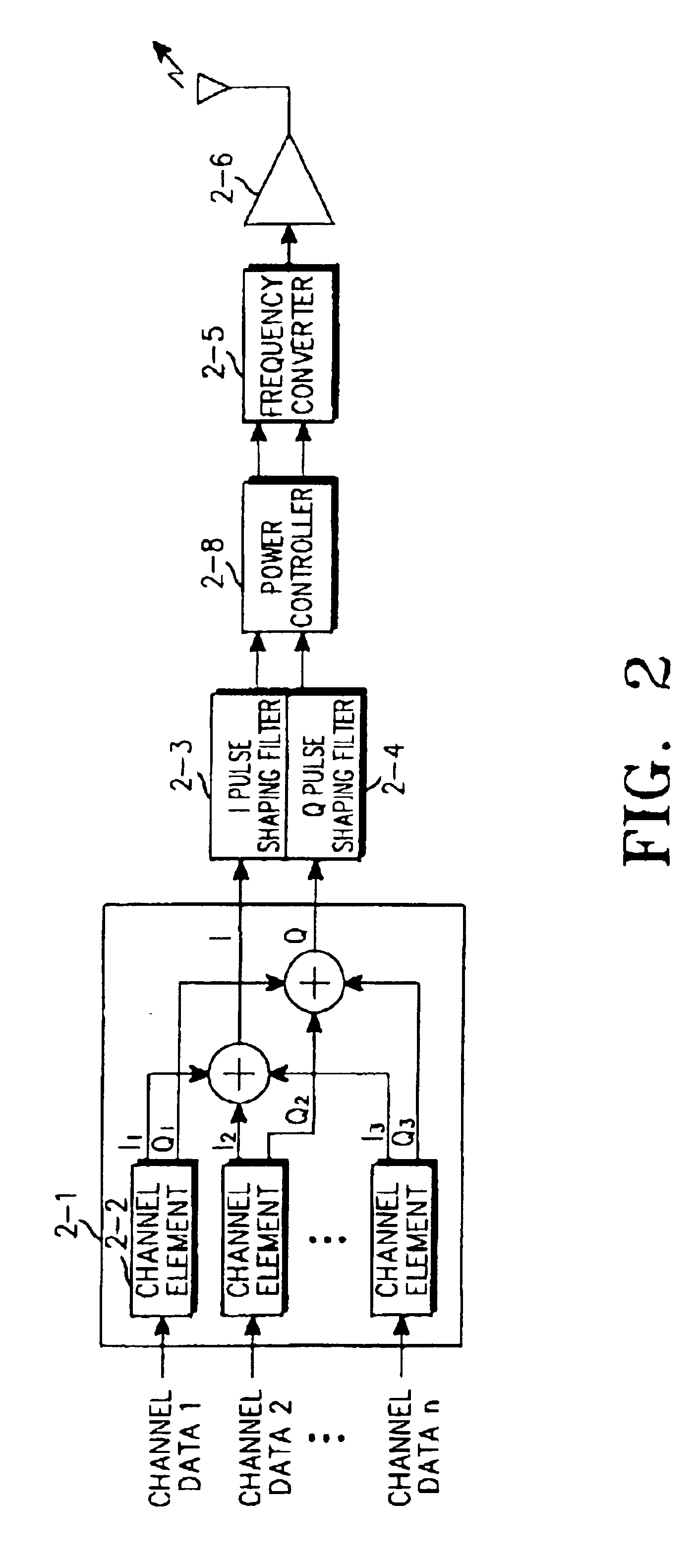
[0045]FIG. 2 is a block diagram of a BS transmitter in a mobile communication system using a single FA according to an embodiment of the present invention.

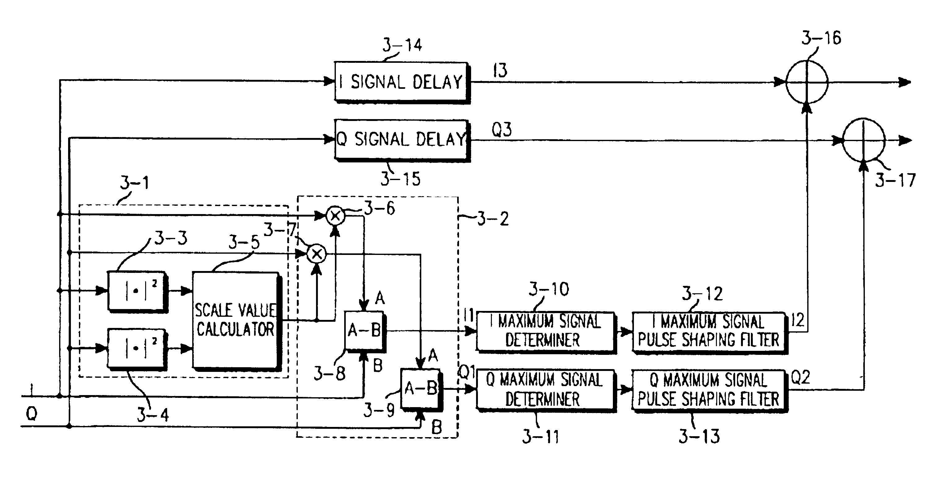
[0046]Referring to FIG. 2, the transmitter includes a channel device group 2-1 having at least one channel element 2-2, I and Q pulse shaping filters 2-3 and 2-4, a frequency converter 2-5, and a power amplifier 2-6. Especially a power controller 2-8 is disposed between the pulse shaping filters 2-3 and 2-4 and the frequency converter 2-5 to perform a CFR algorithm according to the present invention.

[0047]In operation, the channel device group 2-1 generates I and Q channel baseband signals by performing encoding, modulation and channelization on each channel data. Particularly in a CDMA system, the I and Q channel signals are the I and Q channel chip-level sums of common control signals and user data for multiple users.

[0048]Since a serious output power change occurs in a system that transmits the sum of multiple channel sign...

second embodiment

[0076

[0077]The second embodiment of the present invention is applied to a BS in a mobile communication system supporting multiple FAs.

[0078]FIG. 13 is a block diagram of a BS transmitter in the mobile communication system using multiple FAs according to the second embodiment of the present invention.

[0079]Referring to FIG. 13, the transmitter includes a channel device unit 13-1, a pulse shaping filter unit 13-2, and a power amplifier 13-4. Especially, a multi-FA power controller 13-3 is disposed between the pulse shaping filter unit 13-2 and the power amplifier 13-4 to control the PAPRs of original FA signals.

[0080]In operation, the channel device unit 13-1 has a plurality of channel element groups corresponding to the FAs and each channel element group includes channel devices that are the same in configuration as the channel element group 2-1 illustrated in FIG. 2 and perform encoding, modulation and channelization on each FA baseband signal. The channel device unit 13-1 controls ...


PUM


Abstract

An apparatus and method for maximizing the efficiency of a power amplifier by reducing the PAPR of a BS in a mobile communication system. A power controller between I and Q channel pulse shaping filters and a frequency converter calculates cancellation signals for signal pulses that increase the PAPR at each sampling period, pulse-shape-filters cancellation signals at the highest levels among the cancellation signals, and adds the filtered cancellation signals to the original signals. Thus, spectral regrowth outside a signal frequency band is suppressed. In the case of a system supporting multiple frequency allocations, the PAPR is controlled for each FA according to its service class. Therefore, minimum system performance is ensured and power use efficiency is increased.

Description

PRIORITY[0001]This application claims priority to an application entitled “Apparatus and Method for Controlling Transmission Power in a Mobile Communication System” filed in the Korean Industrial Property office on Jul. 13, 2001 and assigned Serial No. 2001-42312, the contents of which are hereby incorporated by reference.BACKGROUND OF THE INVENTION[0002]1. Field of the Invention[0003]The present invention relates generally to a mobile communication system, and in particular, to an apparatus and method for reducing the peak-to-average power ratio (PAPR) of a base station (BS) in a mobile communication system.[0004]2. Description of the Related Art[0005]As is known, a BS uses an RF (Radio Frequency) power amplifier for amplifying an RF signal including voice and data destined for a mobile station (MS). The RF amplifier is the most expensive device in the entire system and thus a significant component to be considered to reduce system cost. This RF amplifier should be designed to meet...

Claims


Application Information

Patent Timeline
Patent Type & Authority Patents(United States)
IPC IPC(8): H04B7/005H04L27/36H04B1/707H04B7/26H04J13/00H04W52/04H04W52/26H04W52/30H04W52/36H04W52/52
CPCH04B1/0475H04W52/52H04W52/26H04W52/36H04W72/0453Y02B60/50
Inventor JO, SUNG-KWONYANG, SANG-HYUNOH, JEONG-TAE
Owner SAMSUNG ELECTRONICS CO LTD
Why Eureka
Eureka Blog
Learn More