Stress and strain analysis method and its equipment

a strain analysis and strain analysis technology, applied in the direction of force measurement, force measurement, force measurement, etc., can solve the problems of inability to obtain individual stress component values sub>1 /sub>and sub>2/sub>, and achieve the effect of detailed stress measuremen

Inactive Publication Date: 2007-08-16
NAT INST OF ADVANCED IND SCI & TECH
View PDF14 Cites 20 Cited by
  • Summary
  • Abstract
  • Description
  • Claims
  • Application Information

AI Technical Summary

Benefits of technology

[0020] Therefore, an object of the present invention is to provide a stress analysis method and stress analysis equipment, which allow a more detailed stress measurement than can be provided by a photoelasticity measurement method alone by using both the photoelasticity measurement method and a stress measurement, which utilizes a mechanoluminescence material, to measure a state of a stress of an object.

Problems solved by technology

With this method, quantitative measurement is possible but in the case of a wide measurement area or a narrow measurement area, a thorough measurement is impossible due to a limit on the number of gauges that can be stuck in the area.
This technique, however, has a fundamental limitation in that it is impossible to obtain individual stress component values σ1 and σ2.

Method used


Image

  • Stress and strain analysis method and its equipment
  • Stress and strain analysis method and its equipment
  • Stress and strain analysis method and its equipment

Examples


Embodiment Construction

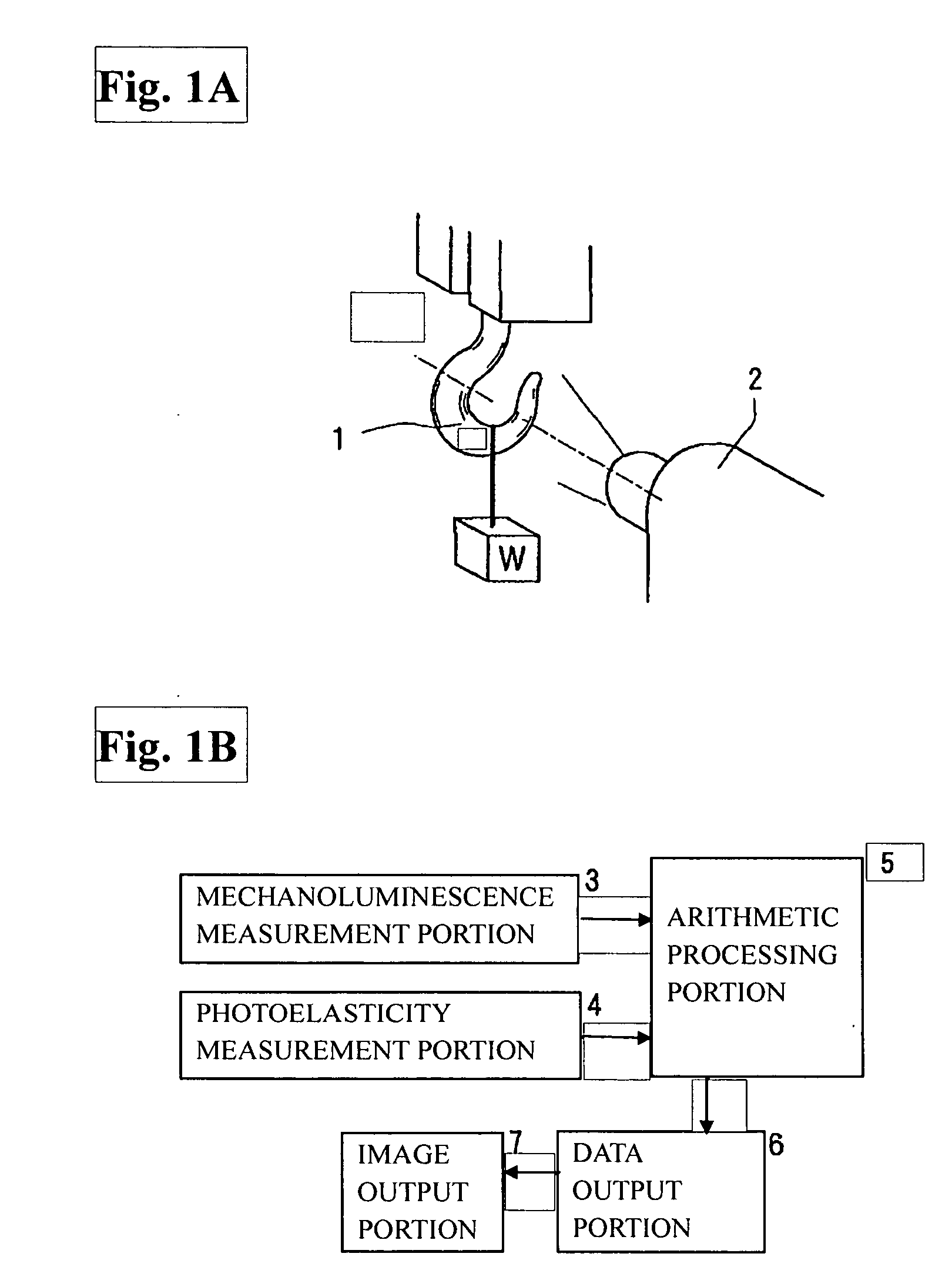
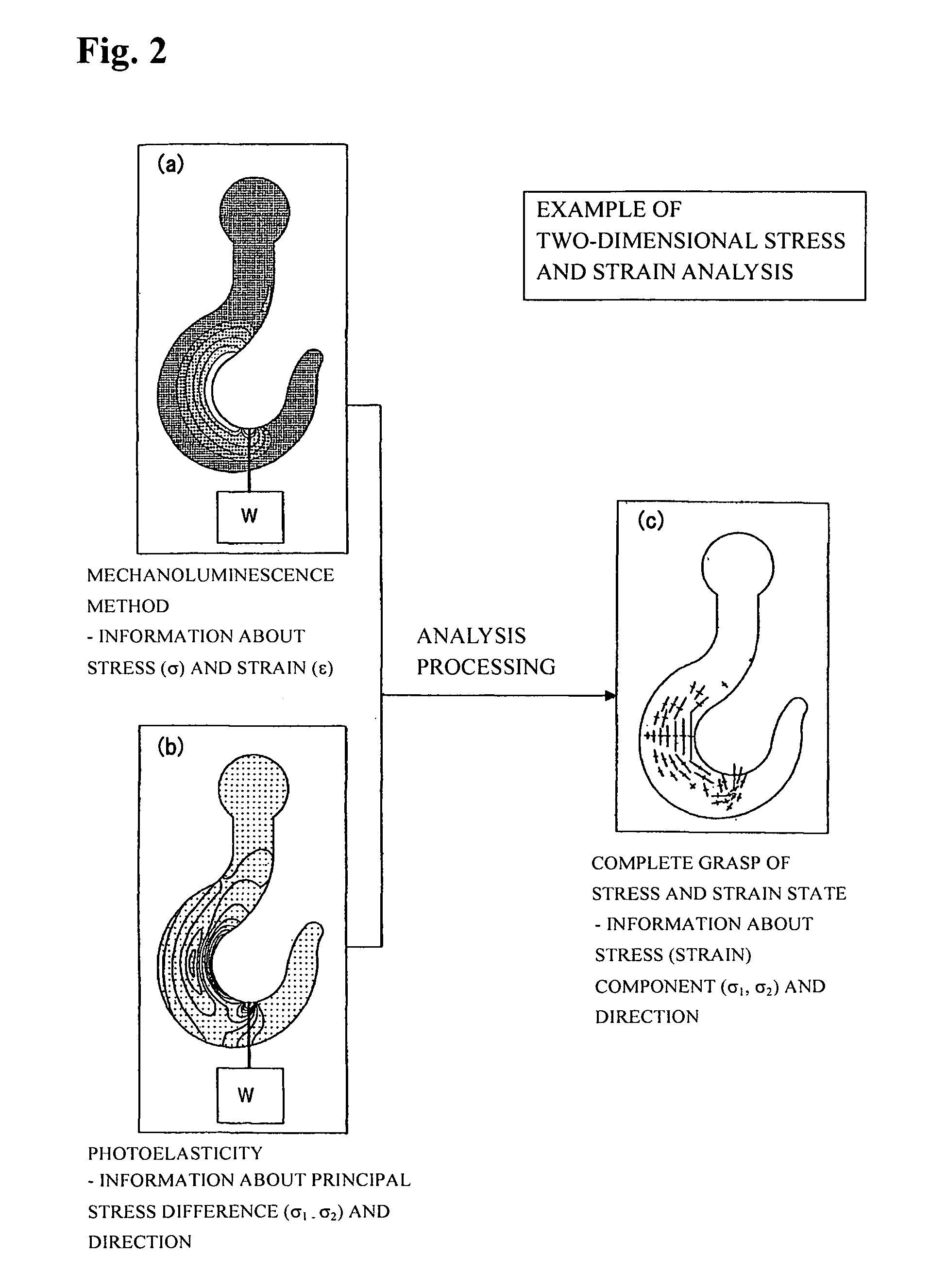
[0033] The exemplary embodiments of the present invention are realized by performing both photoelasticity stress measurement and mechanoluminescence measurement to measure a stress distribution of an object. By performing arithmetic processing or the like using data obtained as a result of the photoelasticity stress measurement and data obtained as a result of the mechanoluminescence measurement, it becomes possible to obtain stress information that cannot be obtained through only one of the measurements.

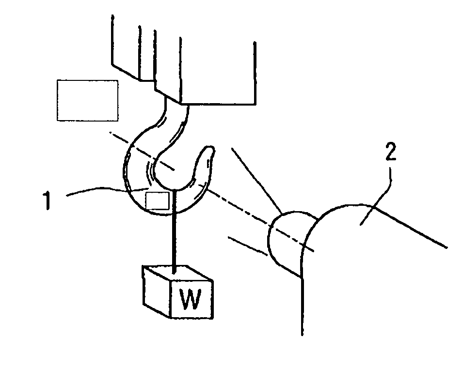
[0034]FIG. 1A shows a case where a load W is applied to a hook 1 as a test target piece. That is, in an exemplary embodiment of the present invention, the hook 1 to which the load is applied is photographed with a camera 2, as shown in FIG 1A. The camera 2 that has conventionally been used in photoelasticity measurement is used to photograph birefringence caused by a stress and a strain that act on the hook 1 (photoelasticity optical system is omitted from the figure). In addition,...


PUM

PropertyMeasurementUnit
stress distributionaaaaaaaaaa
stress analysisaaaaaaaaaa
stressaaaaaaaaaa

Abstract

Provided are a stress analysis method and stress analysis equipment that enable a detailed stress measurement, by using both a photoelasticity measurement method and a stress measurement (mechanoluminescence measurement) which utilizes a mechanoluminescent substance to measure a stress state of an object. Physical quantities that are measurable include individual principal stress component and a principal stress direction. The photoelasticity measurement method alone cannot measure individual principal stress component values.

Description

BACKGROUND OF THE INVENTION [0001] 1. Field of the Invention [0002] The present invention relates to a stress and strain analysis method and stress and strain analysis equipment that enable a more detailed determination of a stress and strain state of an object. [0003] 2. Description of the Related Art [0004] Safety from a dynamic viewpoint in various products such as airplanes, trucks, piping in power plants, bridges, and orthopedic and dental implants is a basic and indispensable element for realizing a worry-free and safe society. Also, for realization and evaluation of safety of the products from the dynamic viewpoint, a stress and strain measurement technology plays an important role. [0005] Conventionally, a strain gauge method has been used for measurement of a stress distribution. In the strain gauge method, many strain gauges are stuck to a surface of a measurement target object, and a stress and strain distribution is determined based on an output signal from each strain g...

Claims


Application Information

Patent Timeline
Patent Type & Authority Applications(United States)
IPC IPC(8): G01N3/08
CPCG01N3/068G01N2203/0033G01N3/14
Inventor HYODO, KOJIXU, CHAO-NANYAMANE, TAKASHIAKAMATSU, MOTOYUKIYOKOGAWA, YOSHIYUKIKAMEYAMA, TETSUYA
Owner NAT INST OF ADVANCED IND SCI & TECH
Why Eureka
Try Eureka