Servo motor with large rotor inertia

a servo motor and large rotor technology, applied in the field of servo motors, can solve the problems of increasing the cost, and increasing the number of mold dies for the stator, and achieve the effect of increasing the rotation inertia of the rotor

Active Publication Date: 2007-08-16
DELTA ELECTRONICS INC
View PDF9 Cites 5 Cited by
  • Summary
  • Abstract
  • Description
  • Claims
  • Application Information

AI Technical Summary

Benefits of technology

[0012] an inertia disk fixed to the rotation shaft of the rotor, wherein the inertia disk is rotated to increase rotation inertia of the rotor when the stator is magnetized to rotate the rotor.

Problems solved by technology

The number of mold die for the stator 21a is also increased and the cost is also increased.

Method used


Image

  • Servo motor with large rotor inertia
  • Servo motor with large rotor inertia
  • Servo motor with large rotor inertia

Examples


Embodiment Construction

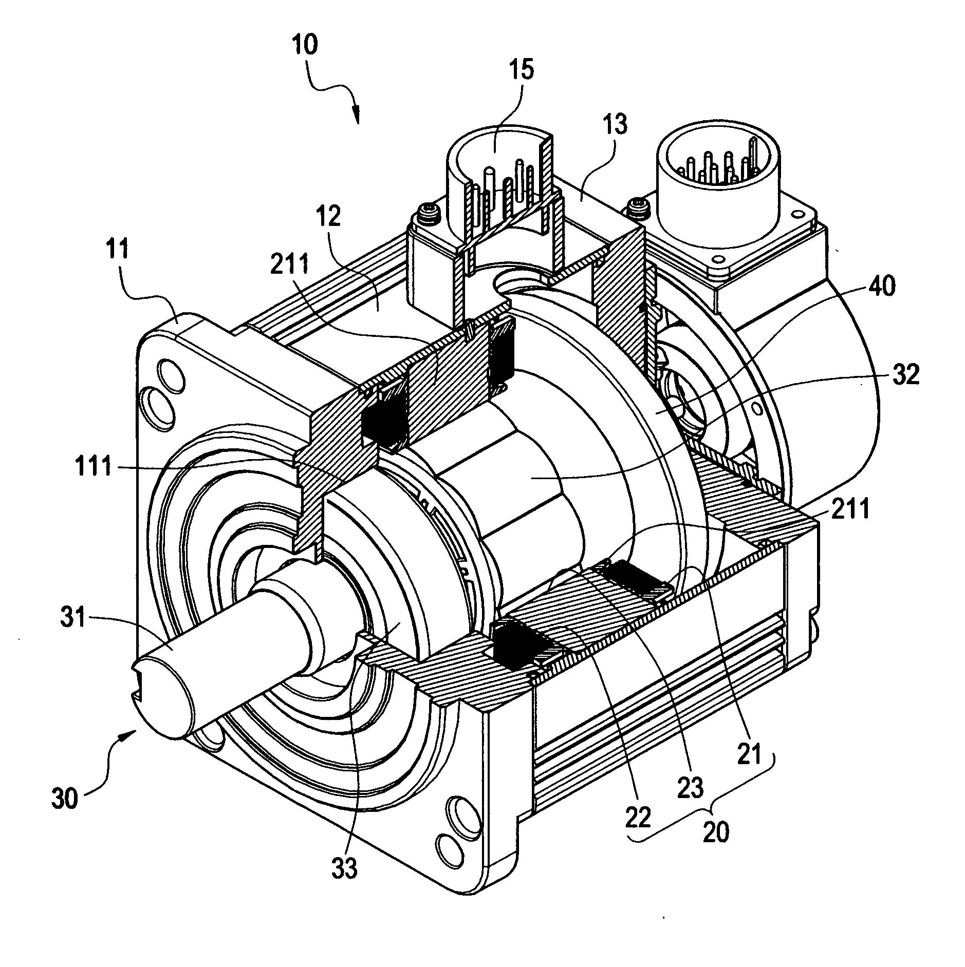
[0021] With reference to FIGS. 3 and 4, the present invention provides a servo motor with high inertia. The servo motor mainly comprises a casing 10, a stator 20, a rotor 30 and an inertia disk 40.

[0022] The casing 10 comprises a front shell 11, a cylindrical middle shell 12 connected to rear side of the front shell 11, and a rear shell 13 connected to rear side of the middle shell 12. A closed and hollow accommodating chamber 14 is defined within the front shell 11, the cylindrical middle shell 12 and the rear shell 13. As shown in FIG. 4, axial stages 111 and 131 are formed on center of the front shell 11 and the rear shell 13 and opposite to each other. Moreover, terminal stage 15 is connected to topside of the middle shell 12 for the connection of external power cord.

[0023] The stator 20 is arranged in the accommodating chamber 14 of the casing 10 and directly fixed to inner wall of the middle shell 12. The stator 20 comprises a ring 21 and a plurality of silicon steel plates ...


PUM


Abstract

A servo motor with large rotor inertia includes a casing, a stator, a rotor and an inertial disk. The casing includes a hollow chamber and axial stages at front side and rear side thereof. The stator is arranged in the chamber and includes a ring and a plurality of coils around the ring. A through hole is defined at the center of the ring. A rotation shaft of the rotor is fixed to the stage and a magnet body is capped to the rotation shaft, where the magnet body is arranged in the through hole. The inertial disk is fixed to the rotation shaft of the rotor. The rotational inertia of the rotor is increased by rotating the inertial disk when the rotor is rotated by magnetize the stator. Therefore, the inertial disks of various sizes can be fixed to the rotor for matching different load inertia.

Description

BACKGROUND OF THE INVENTION [0001] 1. Field of the Invention [0002] The present invention relates to a servo motor, especially to a servo motor with large rotor inertia. [0003] 2. Description of Prior Art [0004] The major function of servo motor is to drive load and achieve a precise position for the load. The motor and load is generally connected by flexible link to couple the axes of motor and load. The flexible link uses the flexibility pro se to balance the strain and vibration cause by misalignment between motor and load. However, the motor and the load become a dynamic system of two degree of freedom. Therefore, the rotor inertia and the load inertia need good match to achieve good system controllability. The rotor inertia should be carefully chosen for the known load inertia to achieve optimal performance. [0005] Moreover, the rotor inertia is proportional to rotor length and fourth power of rotor radius. There are two approaches for servo motor with the same cross section. T...

Claims


Application Information

Patent Timeline
Patent Type & Authority Applications(United States)
IPC IPC(8): H02K7/02H02K1/00H02K21/22
CPCY02E60/16H02K7/02
Inventor SHU, HONG-CHENGCHEN, CHUN-HUNG
Owner DELTA ELECTRONICS INC
Why Eureka
Try Eureka