Image-based protruded displacement mapping method and bi-layered displacement mapping method using the same

a mapping method and protruding image technology, applied in the field of image-based protruding image mapping method and bi-layered image mapping method, can solve the problems of unsuitable ray tracing method and reverse image warping method for real-time applications, unnatural results may be obtained depending on the application method of the difficulty of applying the triangle mesh generation method to an interactive program

Active Publication Date: 2007-08-23
INFINIXLAB INC
View PDF4 Cites 20 Cited by
  • Summary
  • Abstract
  • Description
  • Claims
  • Application Information

AI Technical Summary

Benefits of technology

The technical effect of this patent is that it provides a way to represent the detailed surface of an object without changing its underlying reference surface or creating new polygons on top. This helps to better show how objects are shaped and can improve design processes for manufacturing products with specific shapes.

Problems solved by technology

The technical problem addressed in this patent is how to accurately represent the details of the surface of an object using image-based displacement mapping techniques without creating issues like overlapping or insufficient representation of certain areas. Existing methods often use a triangulated surface model or a simplified version of Ray Tracing, leading to difficulties in applying them to live programs and producing unnatural results. Additionally, existing methods struggle to account for variations in the thickness of objects and can result in regions being left out of the final render.

Method used


Image

  • Image-based protruded displacement mapping method and bi-layered displacement mapping method using the same
  • Image-based protruded displacement mapping method and bi-layered displacement mapping method using the same
  • Image-based protruded displacement mapping method and bi-layered displacement mapping method using the same

Examples


embodiment

[0119]The present invention can be applied to entertainment information devices, including video game machines and computer game programs, information devices for representing geo-spatial information, and information devices for generating images through computer graphic rendering.

[0120]In particular, if the present invention is applied to the modeling and visualization of actual geo-spatial information, the structure of FIG. 16 can be obtained. In order to represent an urban topographical model using displacement mapping, the ability to represent both a relatively large displacement of base terrain and a relatively small displacement of structures is required. In the characteristics of geographical information, when the displacement of base terrain and the displacement of structures, such as buildings, are represented together, it is difficult to represent the exact shape of each building. It is beneficial to separate the displacement of a building from the displacement of base ter...


PUM


Abstract

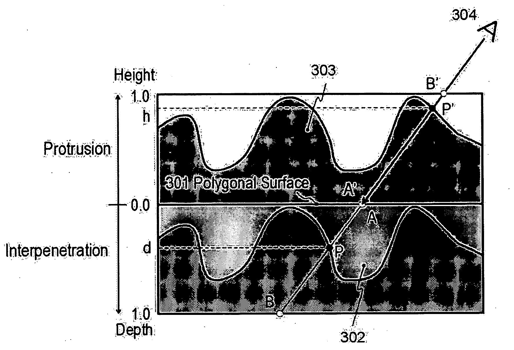
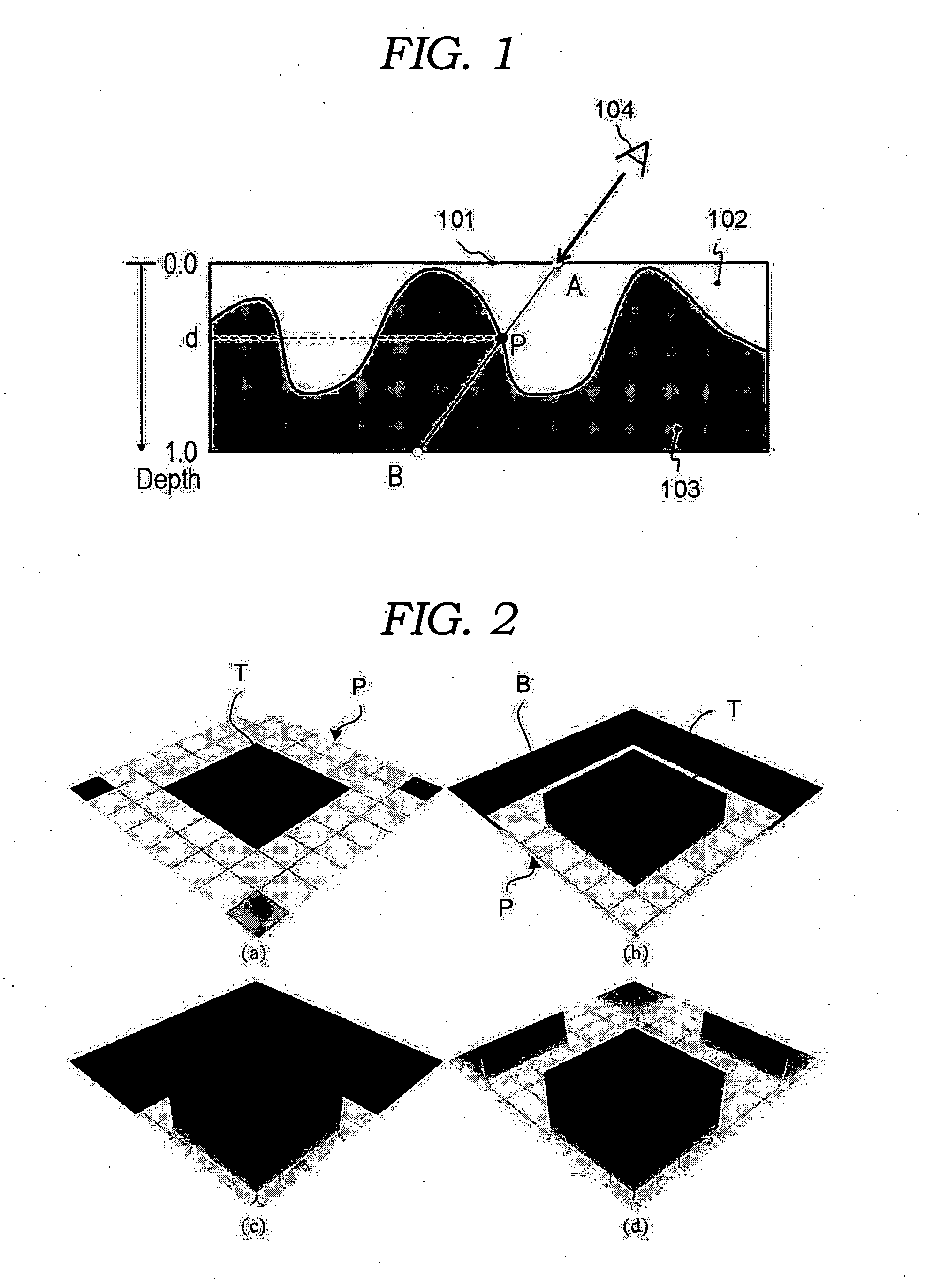
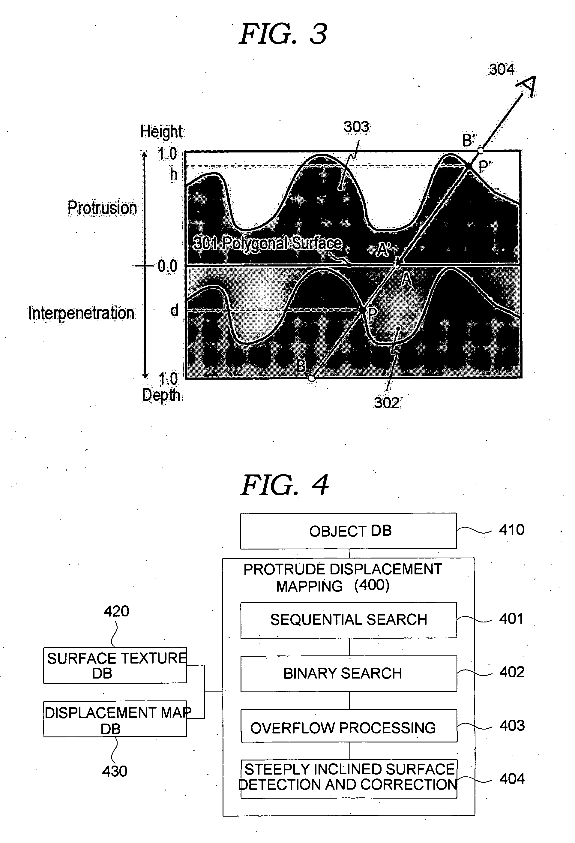
The present invention relates, in general, to technology applied to entertainment information devices, such as video game machines or computer game programs, information devices for representing geo-spatial information, or information devices for performing three-dimensional rendering using computer graphics and, more particularly, to a protruded displacement mapping method, which represents an object as protruding from a surface. In the image-based protruded displacement mapping method of the present invention, an intersection point search step of searching for an intersection point of a surface of a protruding object, defined by the displacement information, and an observers sight line, and displaying the shape of the protruding object on the polygonal surface, is performed. An overflow representation step of adding a separate polygonal surface and representing a shape of the protruding object, corresponding to overflow deviating from a boundary of the polygonal surface, on the added polygonal surface, is performed. A steeply inclined surface step of detecting a steeply inclined surface in the shape of the protruding object is performed. A steeply inclined surface correction step of representing an additional texture on the steeply inclined surface is performed.

Description


Claims


Application Information

Patent Timeline
Owner INFINIXLAB INC
Why Eureka
Try Eureka