Virtual lan system and node device

a virtual hub and node technology, applied in the field of virtual lan systems, can solve the problems of difficult management of virtual hubs, difficulty in starting with a small scale, and need for virtual hubs to provide virtual lans

Inactive Publication Date: 2007-08-23
NEC CORP
View PDF21 Cites 152 Cited by
  • Summary
  • Abstract
  • Description
  • Claims
  • Application Information

AI Technical Summary

Benefits of technology

[0011] It is an object of the present invention to provide a virtual LAN system that does not require a virtual hub, and a node device for the system.

Problems solved by technology

A problem of the prior art is that a virtual hub is needed to provide a virtual LAN.
In other words, since at least one virtual hub is needed even when providing a small virtual LAN consisting of a few nodes, in view of operational costs for setting up and managing the virtual hub, starting with a small scale is difficult.
Furthermore, since a communication within the virtual LAN is always via the virtual hub, traffic loads and processing loads on the virtual hub increase proportionally to the traffic within the virtual LAN, leading to a scalability problem.
Furthermore, the virtual LAN itself cannot be used in the event of a failure of the virtual hub and in the event of a failure of a link where the virtual hub is contained in a backbone network.
In other words, since the virtual hub becomes a single failure point, there is a problem on the reliability of a system.

Method used


Image

  • Virtual lan system and node device
  • Virtual lan system and node device
  • Virtual lan system and node device

Examples


embodiment

[0074] Next, an embodiment of the present invention will be described by referring to drawings. Such an embodiment corresponds to an embodiment for implementing the present invention.

[0075] In the embodiment, a virtual LAN is constructed using the grid graph topology 202 shown in FIG. 4, and, in the initial status, this topology consists of eight nodes shown in state 301 in FIG. 6.

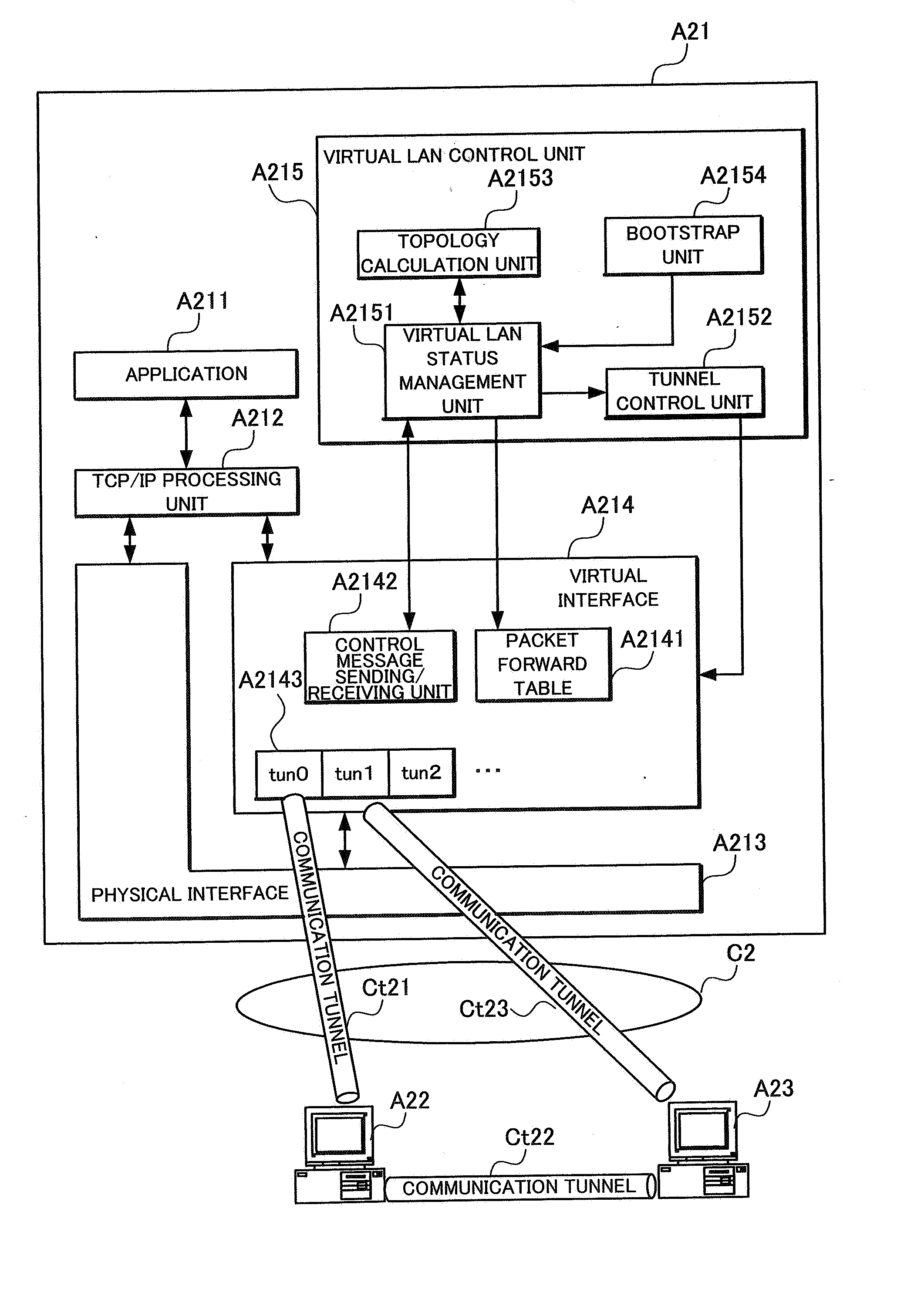
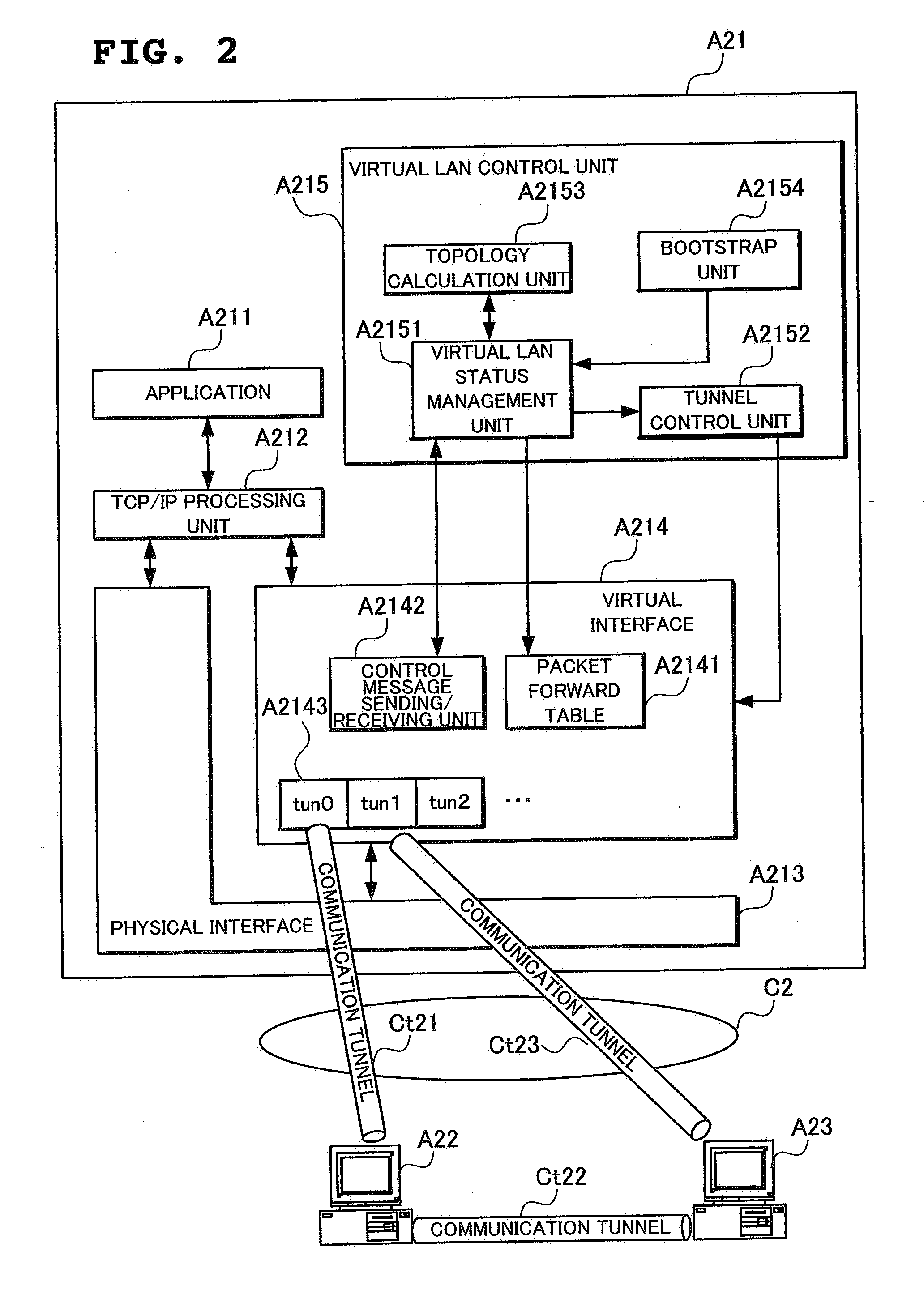
[0076] The node A21 in FIG. 2 newly joins in the virtual LAN. The information needed to join in the virtual LAN is the number of nodes joining in the virtual LAN, and the base IP address of the partner node for which the newly joining node should open a communication tunnel; in the embodiment, these data is resolved using DNS.

[0077] To resolve the number of nodes currently joining in the virtual LAN and the base IP address of the partner node for which the newly joining node should open the communication tunnel, using the DNS, the node about to join in the virtual LAN performs the following operations. ...


PUM


Abstract

A node A21 sets a communication tunnel for encapsulating a data link packet with other nodes joining in a virtual LAN to a peer-to-peer type, and comprises a packet forward table A2141 for forwarding the data link layer packet received from a communication tunnel to another communication tunnel. In addition, the node A21 reconfigures the topology of the virtual LAN using a topology calculation unit A2153 when another node withdrew from the virtual LAN, and opens or removes communication tunnels according to the reconfigured topology using a tunnel control unit A2152.

Description

FIELD OF THE INVENTION [0001] The present invention relates to a virtual LAN system, and more particularly to a virtual LAN system and a node device allowing, in a virtual LAN constructed virtually on a physical network using a communication tunnel, the virtual LAN to be provided without requiring a virtual hub, by setting the communication tunnel between the joining nodes to peer-to-peer type. DESCRIPTION OF THE RELATED ART [0002] As described in Patent Bulletin 3343064 (page 26, FIG. 16), this type of virtual LAN (Local Area Network) system is conventionally used as a system that provides a virtual LAN environment via a pseudo-network adapter and a tunnel server. Nodes joining in a virtual LAN of this type have a virtual adapter (a virtual interface, also referred to as a virtual NIC), and the virtual adapter encapsulates the data link layer net packets (e.g., Ethernetâ„¢ packets) to send and receive the packets between itself and a tunnel server (also referred to as a virtual hub o...

Claims


Application Information

Patent Timeline
Patent Type & Authority Applications(United States)
IPC IPC(8): H04L12/56H04L12/46H04L12/70
CPCH04L12/4633H04L45/02H04L12/4675H04L12/4641
Inventor FUJITA, NORIHITOKOIDE, TOSHIO
Owner NEC CORP
Why Eureka
Try Eureka