Kneeling device

a technology for knees and knees, applied in the field of kneeling devices, can solve the problems of affecting the comfort of kneeling, and affecting the comfort of kneeling, and achieve the effect of convenient storag

Inactive Publication Date: 2007-09-06
GENTLES ALICE JOYCE +1
View PDF21 Cites 19 Cited by
  • Summary
  • Abstract
  • Description
  • Claims
  • Application Information

AI Technical Summary

Benefits of technology

The present invention is a kneeling device that includes a platform made of resilient material and at least one handle that can be attached to the platform. The platform has two depressions for receiving the knees of an individual. The device allows users to use the platform without the handle(s) and can be easily stored. The handle(s) help transfer the weight of the body to the platform, making it easy for the individual to stand or kneel. The technical effect of this invention is to provide a versatile and convenient tool for kneeling and other forms of exercise.

Problems solved by technology

The technical problem addressed in this patent is the pain and damage to the knees caused by traditional kneeling methods, which can be difficult and uncomfortable for individuals with knee problems. The patent describes various kneeling devices that have been developed to address these issues, but each has its own limitations such as being cumbersome, applying pressure unevenly, or requiring a flexible individual. The patent proposes a new kneeling device that overcomes these limitations and provides a more comfortable and efficient solution for individuals who need to kneel for extended periods of time.

Method used


Image

  • Kneeling device
  • Kneeling device
  • Kneeling device

Examples


Embodiment Construction

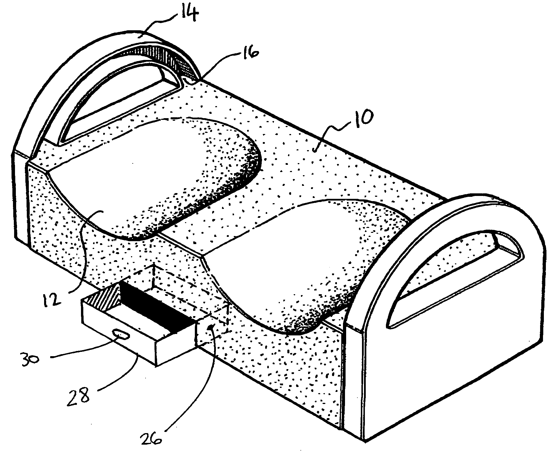
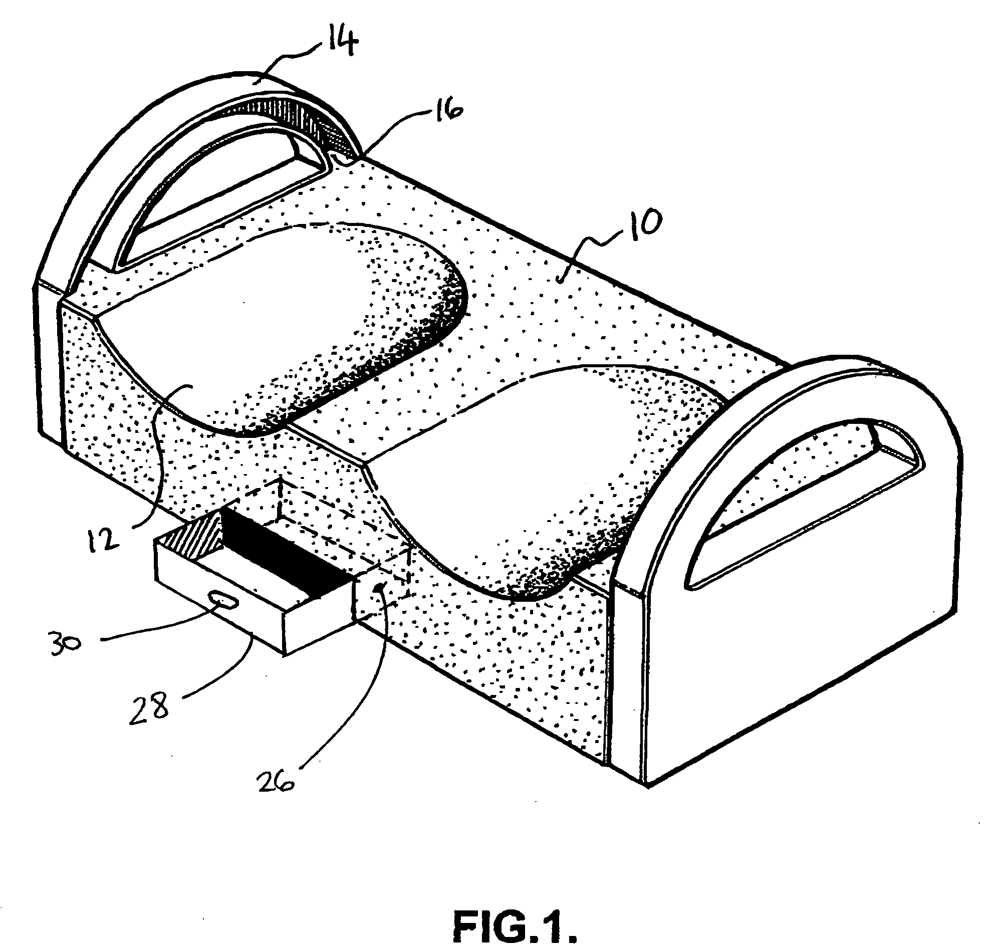
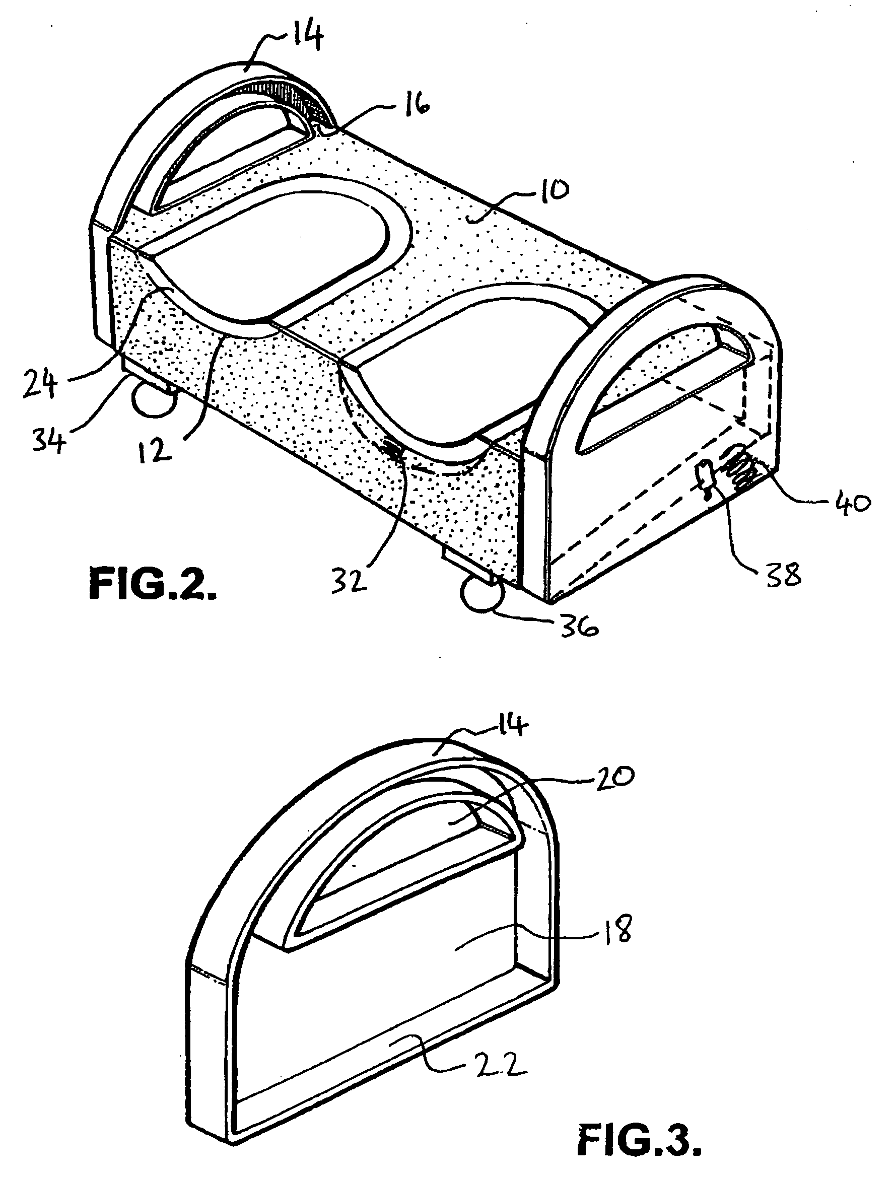
[0026] The preferred embodiment and best mode of the present invention is shown in FIGS. 1-3.

[0027] With reference to FIG. 1, there is provided a kneeling device for assisting an individual to kneel on a surface the device comprising a platform 10 produced from a resilient material and having two depressions 12 formed thereon. The platform may be produced from a number of materials which are substantially resilient and a number of materials will be apparent to one skilled in the art. Preferably, the platform is produced from a foam or compressed rubber material. The platform may additionally have a protective covering or material covering its exterior. It will be evident that such protection will ensure that the platform lasts for a reasonable duration of time and will help maintain its appearance. Preferably, the protective covering or material is resistant to one or more of the following: moisture, stains and high temperature. It will be evident that “high temperature” means temp...


PUM


Abstract

A kneeling device comprising a platform produced from a resilient material, and handles capable of releasably interlocking with the ends of the platform, the platform further having two depressions formed therein for receiving knee pads for accommodating the knees of an individual.

Description


Claims


Application Information

Patent Timeline
Owner GENTLES ALICE JOYCE
Why Eureka
Try Eureka