Vacuum Cleaner with Motor Cooling Air Filtration

a vacuum cleaner and motor technology, applied in the field of vacuum cleaners, can solve the problems of affecting the cleaning effect of the vacuum cleaner, affecting the cleaning effect, and adding the expense of the filter to the vacuum cleaner,

Inactive Publication Date: 2007-09-13
BISSELL HOMECARE
View PDF10 Cites 80 Cited by
  • Summary
  • Abstract
  • Description
  • Claims
  • Application Information

AI Technical Summary

Problems solved by technology

As the air passes through the motor, carbon dust discharged from the motor brushes can become entrained in the air and thus also exhausted from the vacuum cleaner, leading to contamination of the home environment.
A filter can be placed at the inlet or exhaust port to remove carbon dust from the motor cooling air, however, this filter adds expense and bulk to the vacuum cleaner.

Method used


Image

  • Vacuum Cleaner with Motor Cooling Air Filtration
  • Vacuum Cleaner with Motor Cooling Air Filtration
  • Vacuum Cleaner with Motor Cooling Air Filtration

Examples


Embodiment Construction

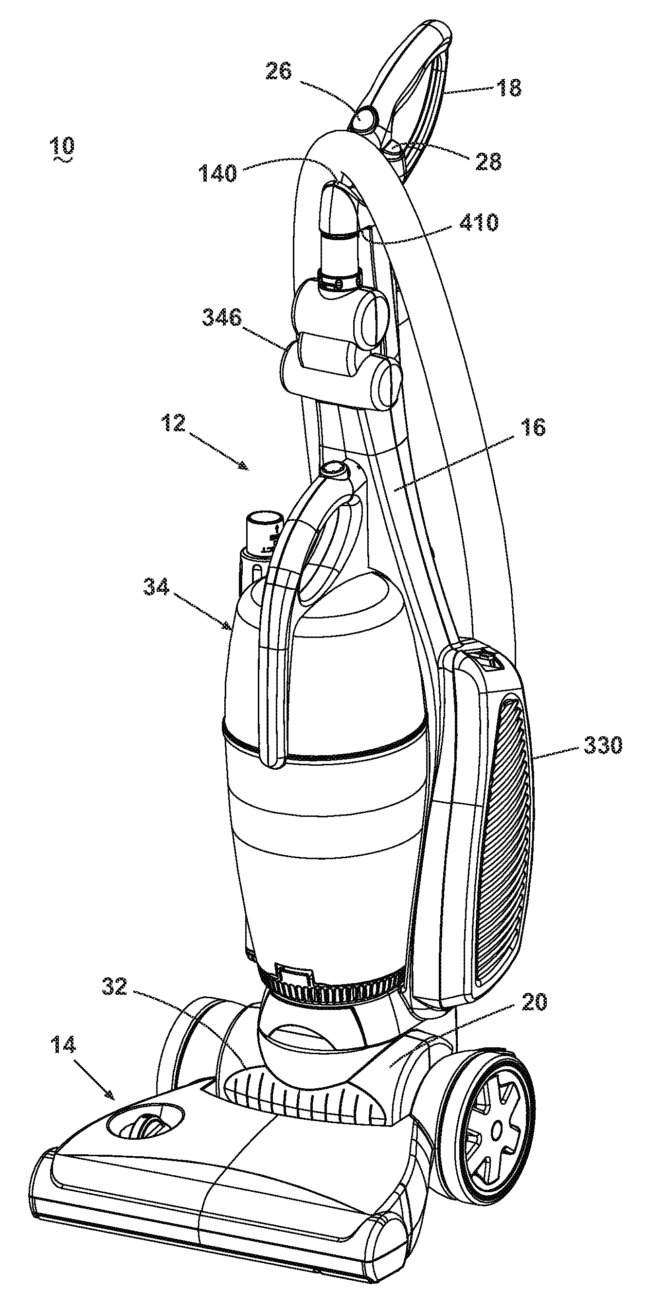
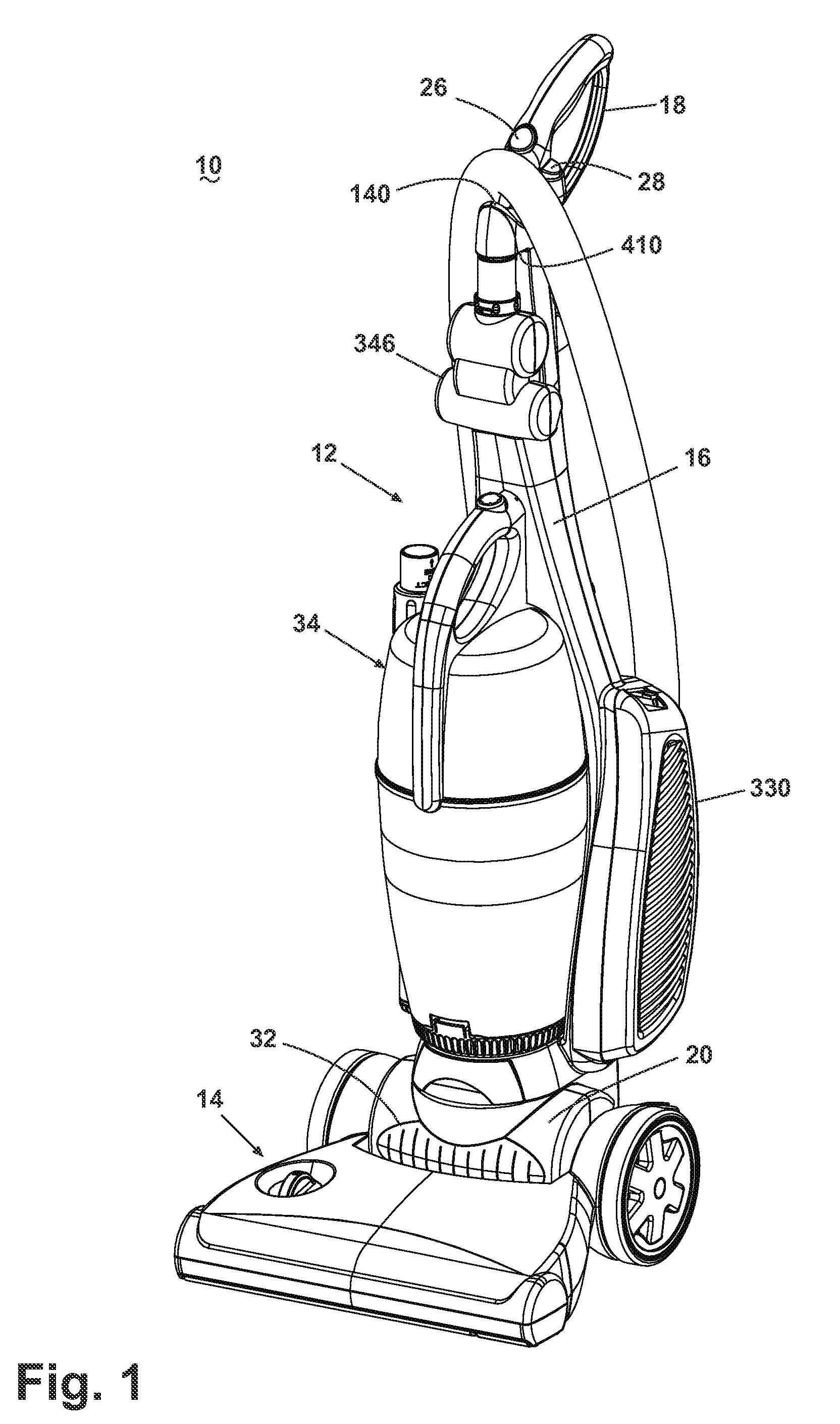
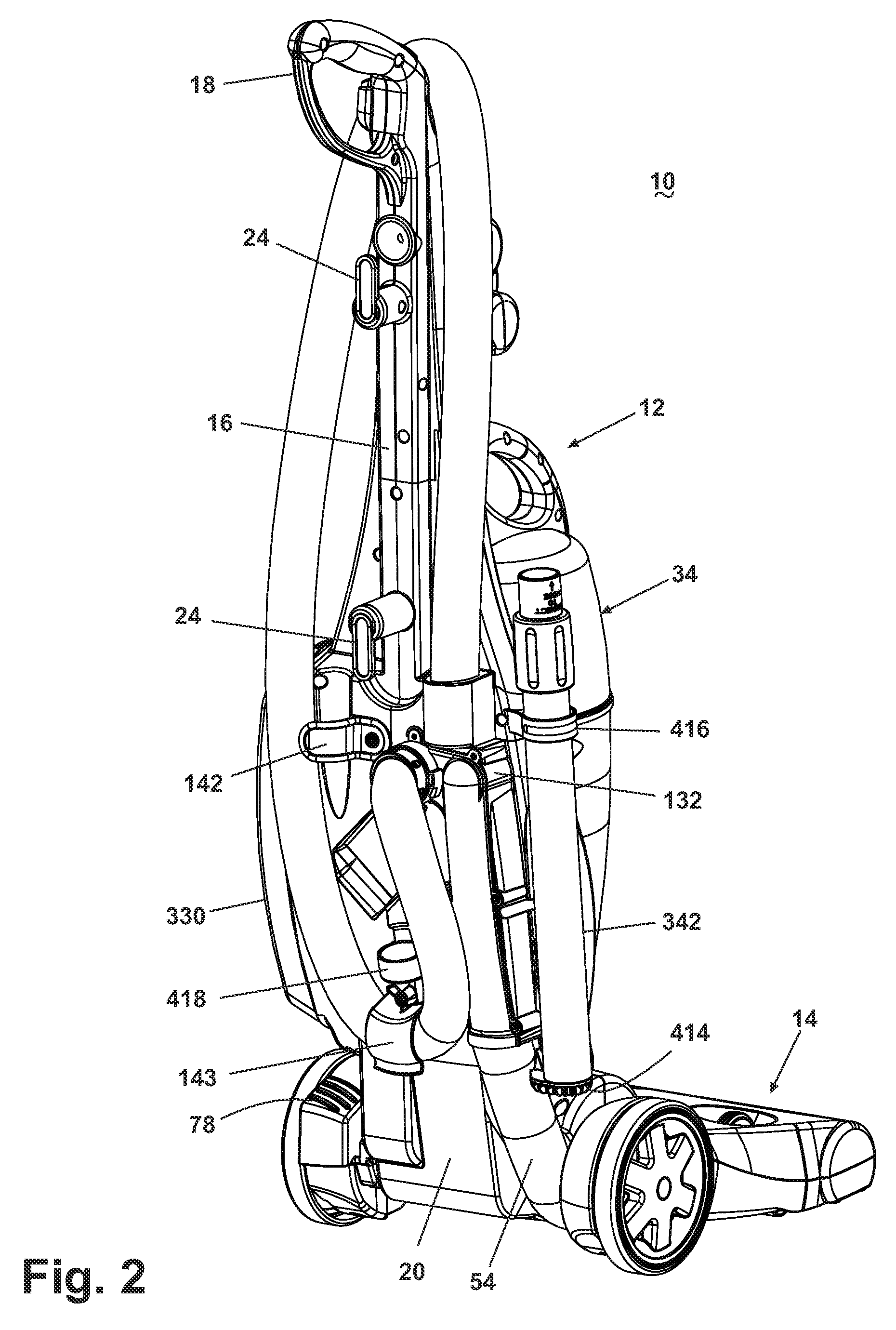
[0054]Referring to the drawings, and in particular to FIGS. 1-2, an upright vacuum cleaner 10 according to the present invention comprises an handle assembly 12 pivotally mounted to a cleaning head or foot assembly 14. The handle assembly 12 further comprises a primary support section 16 with a closed-loop handgrip 18 on one end to facilitate movement by a user. The handgrip 18 is preferably overmolded with a soft low durometer material for providing a comfortable grip for the user. A motor cavity 20 is formed at an opposite end of the handle assembly 12 and houses a source of suction, illustrated herein as a vertically-oriented motor / fan assembly 22 (FIG. 27). The handle assembly 12 pivots relative to the foot assembly 14 through an axis of rotation formed perpendicular to a shaft within the motor / fan assembly 22. An electric cord (not shown) extending from the motor / fan assembly 22 is stored on a pair of opposed cord wraps 24 provided on the rear of the primary support section 16....


PUM


Abstract

A vacuum cleaner has cooling air from an agitator motor ported to a working air conduit upstream of an inlet to a fan motor assembly.

Description

CROSS REFERENCE TO RELATED APPLICATIONS[0001]This application claims priority to U.S. provisional patent application Ser. No. 60 / 743,454, filed Mar. 10, 2006, which is incorporated herein by reference in its entirety.BACKGROUND OF THE INVENTION[0002]1. Field of the Invention[0003]This invention relates generally to vacuum cleaners. In one of its aspects, the invention relates to a vacuum cleaner that cleans motor cooling air before exhausting the air from the vacuum cleaner.[0004]2. Description of the Related Art[0005]Upright vacuum cleaners having cyclone separators are well-known in the art. These vacuum cleaners may employ a frusto-conical shape separator, while others use high-speed rotational motion of the air / dirt in a cylindrical separator to separate the dirt by centrifugal force. Typically, working air enters and exits at an upper portion of the cyclone separator and the bottom portion of the cyclone separator is used to collect dirt. It is further known to employ multiple ...

Claims


Application Information

Patent Timeline
Patent Type & Authority Applications(United States)
IPC IPC(8): A47L9/10A47L9/16
CPCA47L5/30A61L9/20A47L5/34A47L7/04A47L9/00A47L9/02A47L9/04A47L9/122A47L9/1625A47L9/1641A47L9/1683A47L9/1691A47L9/24A47L9/244A47L9/325A61L9/00A47L5/32
Inventor KREBS, ALAN J.GRIFFITH, AARON P.FESTER, JOSEPH A.
Owner BISSELL HOMECARE
Why Eureka
Try Eureka