Mirror with adjustable detent

a mirror and adjustable technology, applied in the field of external mirrors, can solve the problems of being struck or stuck, and the original mirror is likely to be insufficient to provide a full view to the driver,

Active Publication Date: 2007-09-13
VELVAC
View PDF12 Cites 24 Cited by
  • Summary
  • Abstract
  • Description
  • Claims
  • Application Information

AI Technical Summary

Benefits of technology

[0010]The present invention provides a mirror housing and mounting for a motor vehicle which not only pivots to fold the mirror housing toward the vehicle but also permits an adjustment of the home position of the mirror housing by the end-user.

Problems solved by technology

Since the mirrors extend from the vehicle, they are subject to being struck or sticking objects that pass close to the sides of the vehicle.
When the vehicle is used to tow a trailer, for example, or when a truck has a truck body added onto the frame or a camper body mounted on the truck, the original mirrors are likely to be inadequate to provide a full view to the driver.

Method used


Image

  • Mirror with adjustable detent
  • Mirror with adjustable detent
  • Mirror with adjustable detent

Examples


Embodiment Construction

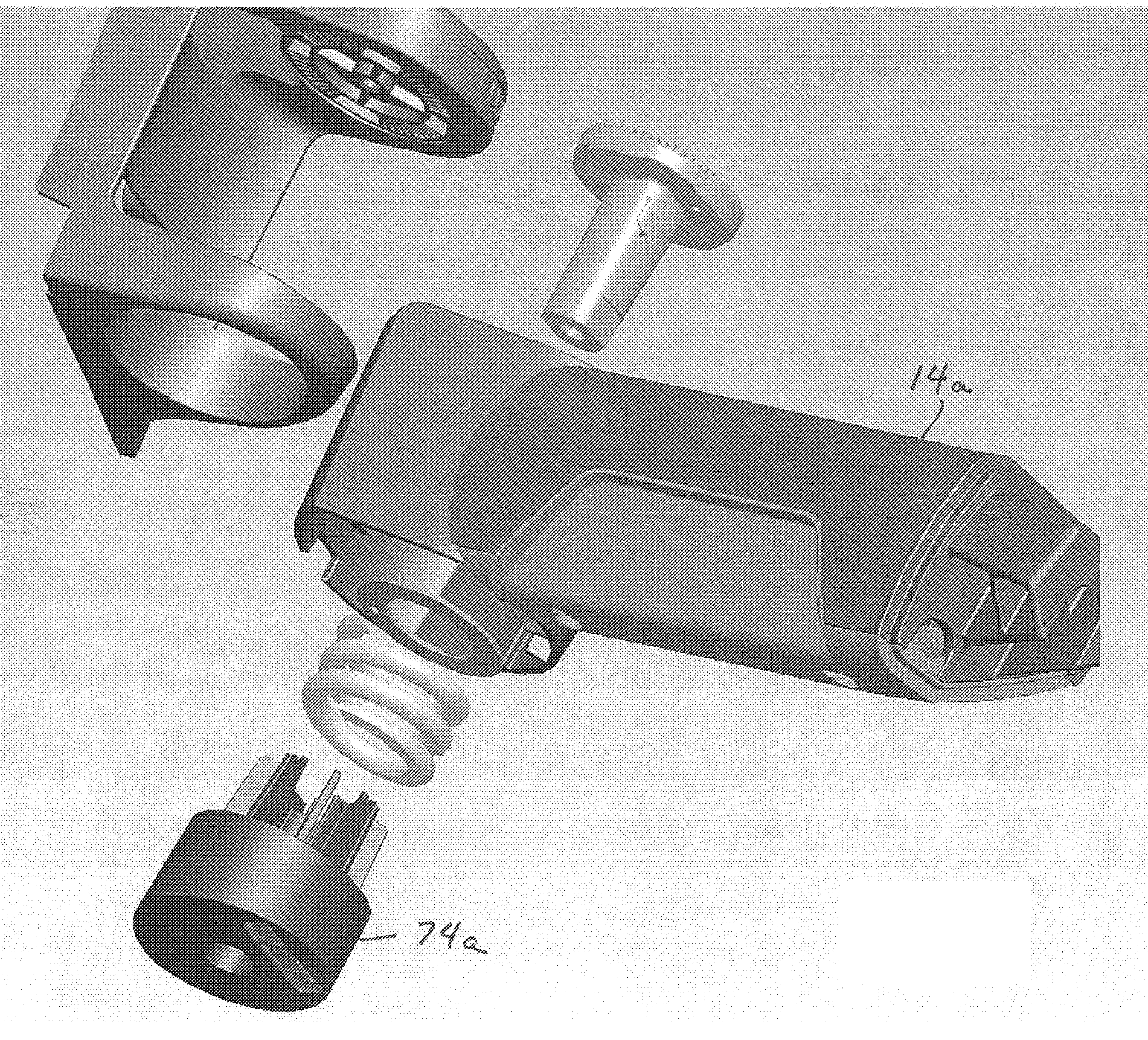
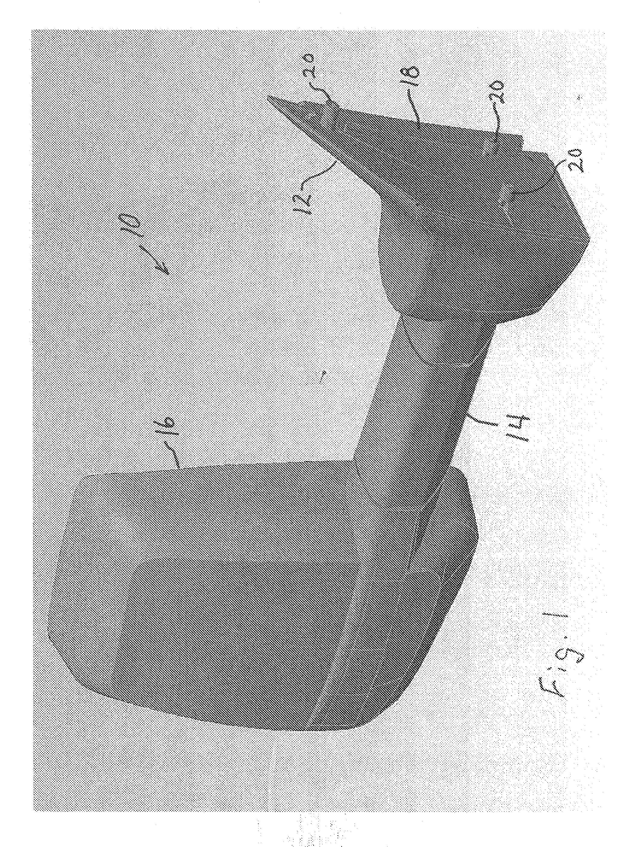
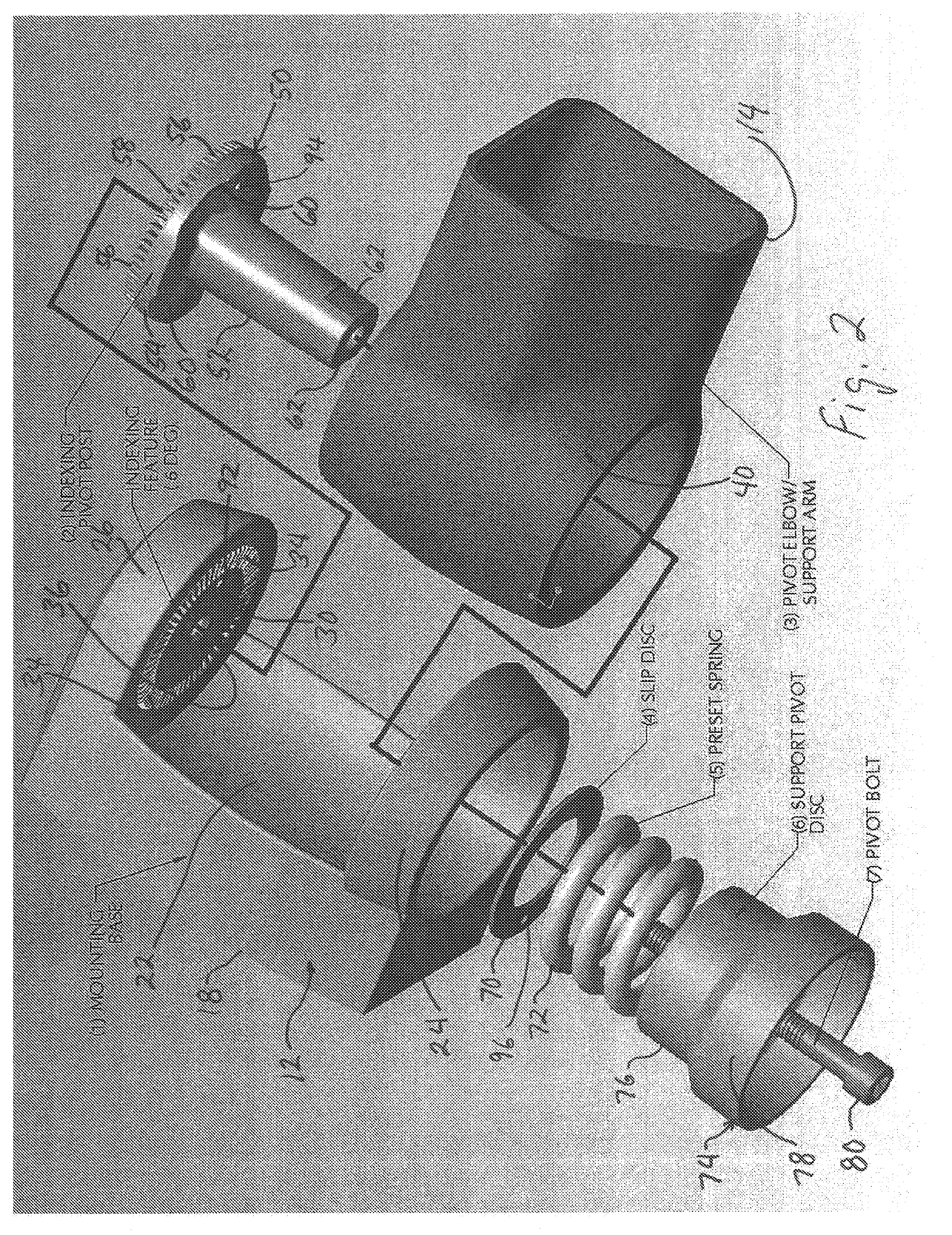
[0017]Referring first to FIG. 1, a mirror unit 10 for a motor vehicle includes a mounting base 12 by which the mirror unit 10 is mounted onto a vehicle. The base 12 supports an arm 14 that extends from the base to hold the mirror away from the vehicle when the mirror unit 10 is mounted to a vehicle. The arm 14 is connected to a mirror housing 16 that holds one or more mirrors. The mirror(s) in the mirror housing 16 may be flat to provide an undistorted view or may be convex to provide a wide angle view to the driver.

[0018]The mounting base 12 includes a mounting surface 18 that is affixed to the vehicle. Preferably, the mounting surface 18 is configured to replace the original mirror unit of the vehicle. Mounting screws 20 are shown on the mounting surface by which the mirror unit is affixed to the vehicle.

[0019]The mounting base 12, arm 14 and mirror housing 16 may be in any of a variety of configurations, shapes and proportions, all of which are within the scope of this invention....


PUM


Abstract

A mirror unit for a vehicle includes a base from which extends an arm holding a mirror housing. The arm is pivotably mounted in the base to permit the mirror to be pivoted toward the vehicle in the event that the mirror is struck, for example. The extended position of the mirror when not folded is defined by a detent in the pivoting movement. The detent position of the mirror is the result of a bolt that presses a spring. The spring in turn presses a hub on the arm against an indexing pivot post, so that ramps on the hub bear against ramps on the indexing pivot post and define the detent position of the mirror. The indexing pivot post has an arrangement of teeth that engage into tooth recesses on the base when pressed thereagainst by the spring. The detent position of the mirror can be changed by the user by the user releasing the bolt to relieve spring pressure on the teeth so that the teeth of the indexing pivot post disengage from the tooth recesses and can be pivoted to a new detent position. The new detent position is ensured by tightening the bolt so that the spring presses the teeth into the tooth recesses.

Description

CROSS REFERENCE TO RELATED APPLICATION[0001]This application claims the benefit of U.S. Provisional Patent Application No. 60 / 7797874, filed Mar. 7, 2006, which is incorporated herein by reference.BACKGROUND OF THE INVENTION[0002]1. Field of the Invention[0003]The present invention relates generally to an external mirror for a motor vehicle and in particular to a mirror mounting and housing permitting pivoting movement of the mirror housing.[0004]2. Description of the Related Art[0005]Motor vehicles, such as trucks, have externally mounted mirrors extending from one or both sides of the vehicle by which the driver can see behind the vehicle. Such mirrors are provided on the vehicle when purchased new and they are also sold as after-market items for replacement of the original mirror mounts. Since the mirrors extend from the vehicle, they are subject to being struck or sticking objects that pass close to the sides of the vehicle. As such, it has become common to provide mirror mounts...

Claims


Application Information

Patent Timeline
Patent Type & Authority Applications(United States)
IPC IPC(8): G02B7/182
CPCB60R1/076
Inventor BRESTER, ROBERT R.ROBERTS, THOMAS L.
Owner VELVAC
Why Eureka
Try Eureka