E-Z wire twister

a wire twister and ez technology, applied in the direction of permanent deformation connection, line/current collector details, electrical equipment, etc., can solve the problems of wires not being twisted properly, difficult to properly twist them using two pairs of pliers, and difficulty in method

Inactive Publication Date: 2007-09-20
DEFRANCE ROBERT VICTOR
View PDF10 Cites 5 Cited by
  • Summary
  • Abstract
  • Description
  • Claims
  • Application Information

AI Technical Summary

Benefits of technology

[0008]The present invention relates to an improved means to twist a plurality of wires toget

Problems solved by technology

With this method, however, the ends of the wires prior to twisting are widely spread apart making it very difficult to twist them properly using two pair of pliers.
In addition, often times the wires a

Method used


Image

  • E-Z wire twister
  • E-Z wire twister
  • E-Z wire twister

Examples


Embodiment Construction

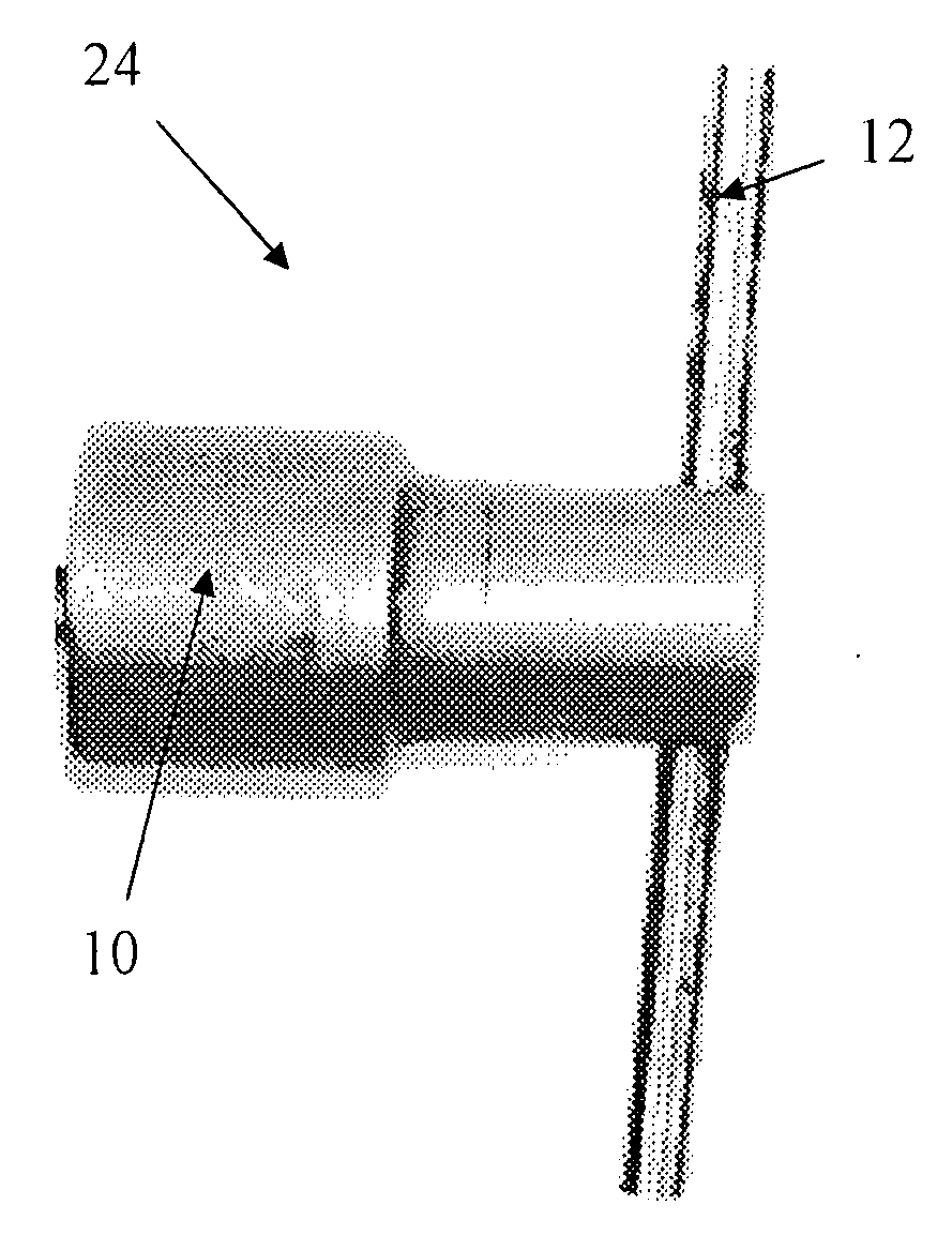
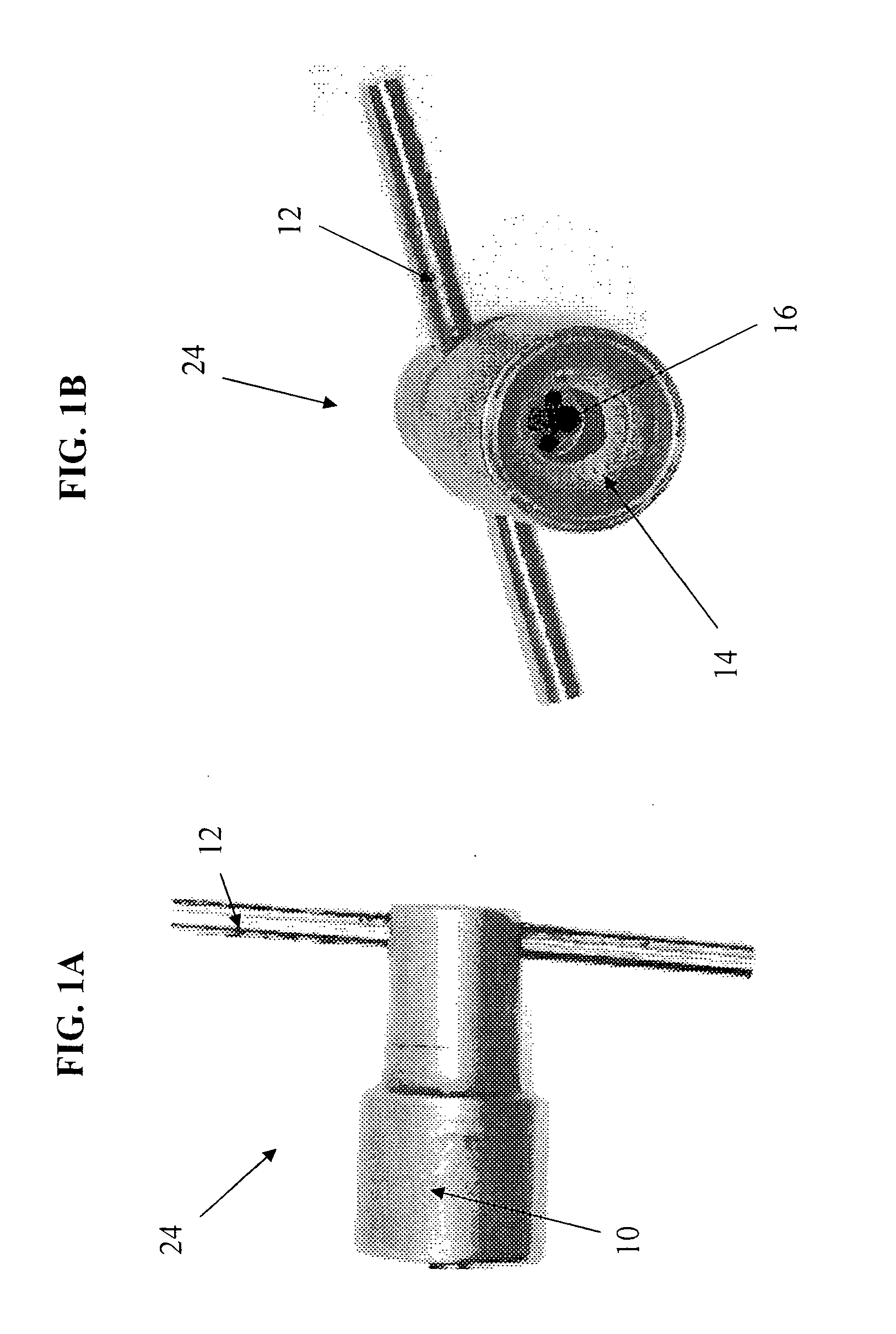
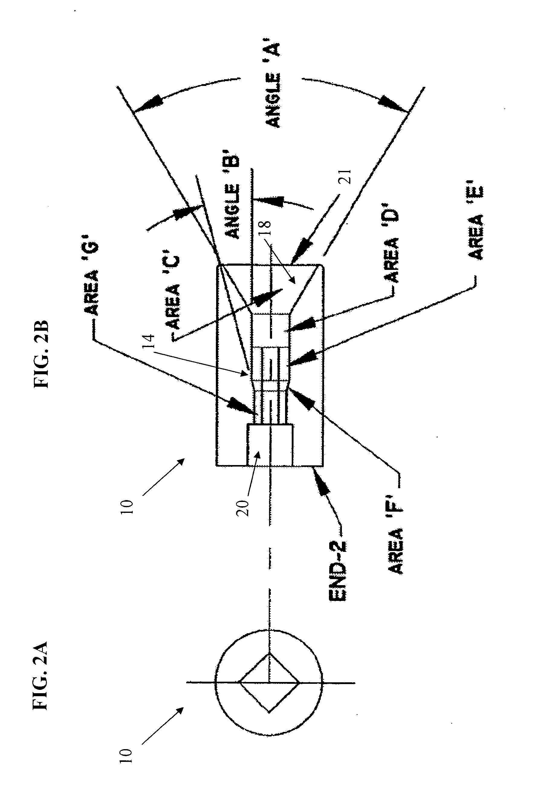
[0025]The present invention is a wire twister used for twisting a plurality of metal or plastic wires together. The wire twister according to the present invention is designed based on a socket concept, similar to a mechanical socket tool. As depicted in FIGS. 1A and 1B, the wire twister or tool 24 comprises a twister head or body portion 10 and a twister rod or gripping portion 12. The twister rod 12 can be inserted into the twister head 10 such that it is substantially perpendicular to the twister head 10. Other means for twisting the head 10 may be utilized if suitable for the purpose. For example a ratchet device may be used and inserted into a standard type ratchet opening as shown in FIG. 2A.

[0026]A cavity 14 inside the twister head 10 is specifically designed to receive the wires and re-arrange them prior to twisting. FIG. 1B, which is a front view of the twister head 10 of tool 24 of the present invention and shows the cavity 14 consisting of several stages of intersecting c...


PUM

PropertyMeasurementUnit
Lengthaaaaaaaaaa
Shapeaaaaaaaaaa

Abstract

The present invention relates to a tool for twisting a plurality of wires together. The tool includes a body portion having a cavity that includes a plurality of contiguous openings to receive a plurality of wires. The tool also includes a gripping portion for gripping the tool. The body portion holds the plurality of wires in a fixed position relative to one another. Rotation of the gripping portion in a clockwise or counterclockwise direction rotates the body portion in a clockwise or counter clockwise direction thereby twisting the plurality of wires together. The gripping portion may be a rod that can be is inserted substantially perpendicularly into the body portion.

Description

RELATED APPLICATIONS[0001]This application claims priority to U.S. Provisional Application Ser. No. 60 / 781,651, filed on Mar. 14, 2006.BACKGROUND OF THE INVENTION[0002]1. Field of the Invention[0003]The present invention relates to joining electrical wires or conductors. More specifically, the invention relates to an improved means of twisting a plurality of wires together.[0004]2. Background of the Invention[0005]In the electrical industry, conductors or wires carry current (electricity) from the power source to the device that is to be powered. Because of the limited length of conductors, the ends have to be properly joined or spliced in order to conduct the amount of electricity required. These connections can be made using various methods such as, for example: 1) by crimping on a compression sleeve; 2) using a mechanical clamping connector; 3) with a soldered joint; or 4) with a wire nut. In all of the previous connection methods, the wire has to be prepared. This procedure is u...

Claims


Application Information

Patent Timeline
IPC IPC(8): B21F15/04
CPCB21F15/04H01R43/033H01R4/12
Inventor DEFRANCE, ROBERT VICTOR
Owner DEFRANCE ROBERT VICTOR
Why Eureka
Try Eureka