
Multi-purpose patient chair

a patient chair and multi-purpose technology, applied in the field of patient chairs, can solve the problems of misplacing the push bar, affecting the mechanism controlling the positioning of the back rest interferes to some degree with the radiolucent window of the back rest, etc., and achieves efficient operation.

Active Publication Date: 2005-06-30
WINCO MFG
View PDF8 Cites 37 Cited by
  • Summary
  • Abstract
  • Description
  • Claims
  • Application Information

AI Technical Summary

Benefits of technology

[0009] The prior art has also failed to provide an efficiently functioning foot platform at the end of leg support sections. This invention provides such a medical chair comprising a seat section; a leg support section pivotally secured to said seat section such that it may selectively extend from said seat section at desired positions in relation thereto; and a leg support actuator that functions to adjust the position of said leg support section in relation to said seat section, wherein the position of said leg support section may range from substantially perpendicular to the plane of said seat section, in a chair configuration, to substantially parallel to the plane of said seat section, in a stretcher configuration; a foot rest section pivotally secured to said leg support section about an axis and providing a foot platform that remains substantially parallel to the plane of said seat section as said leg support actuator functions to adjust the position of said leg support section in relation to the plane of said seat section.
[0010] Each embodiment above, alone or in any combination, lends itself to an improved means for positioning a patient in radiographic and fluoroscopic machines (RF machines). More broadly, this invention provides a method for performing radiographic and fluoroscopic procedures on a patient, the method comprising the steps of supporting the patient in a medical chair comprising a seat section, a radiolucent back rest pivotally secured to said seat section such that it may selectively extend from said seat section at desired positions in relation thereto; and a remote control that controls the positioning of said radiolucent back rest relative to said seat section so that said radiolucent back rest is positionable from points distant from the medical chair; provisionally positioning the medical chair in a radiographic or fluoroscopic machine so as to provisionally position the patient supported thereon for a radiographic or fluoroscopic procedure; and adjusting the positioning of the medical chair and patient supported thereon with said remote control after said step of provisionally positioning the medical chair.

Problems solved by technology

In medical chairs of the prior art, the mechanisms controlling the positioning of the back rest interfered to some degree with the radiolucent window of the back rests.
The prior art has also provided medical chairs having transport push bars that are removable to provide a radiolucent back rest, but the removal of the push bar is an added burden, and misplacing the push bar is common.
The prior art has also failed to provide an efficiently functioning foot platform at the end of leg support sections.

Method used


Image

  • Multi-purpose patient chair
  • Multi-purpose patient chair
  • Multi-purpose patient chair

Examples


Embodiment Construction

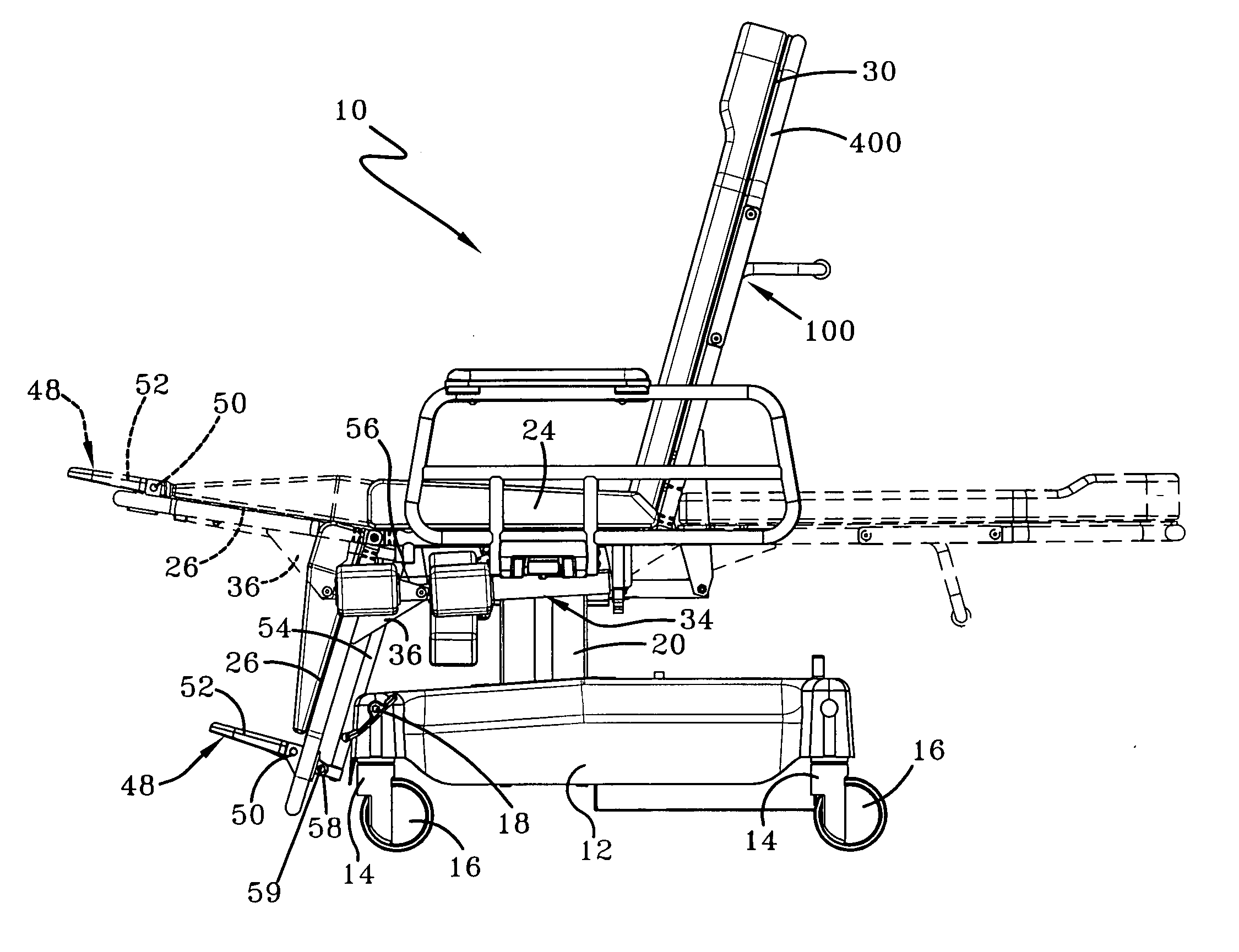
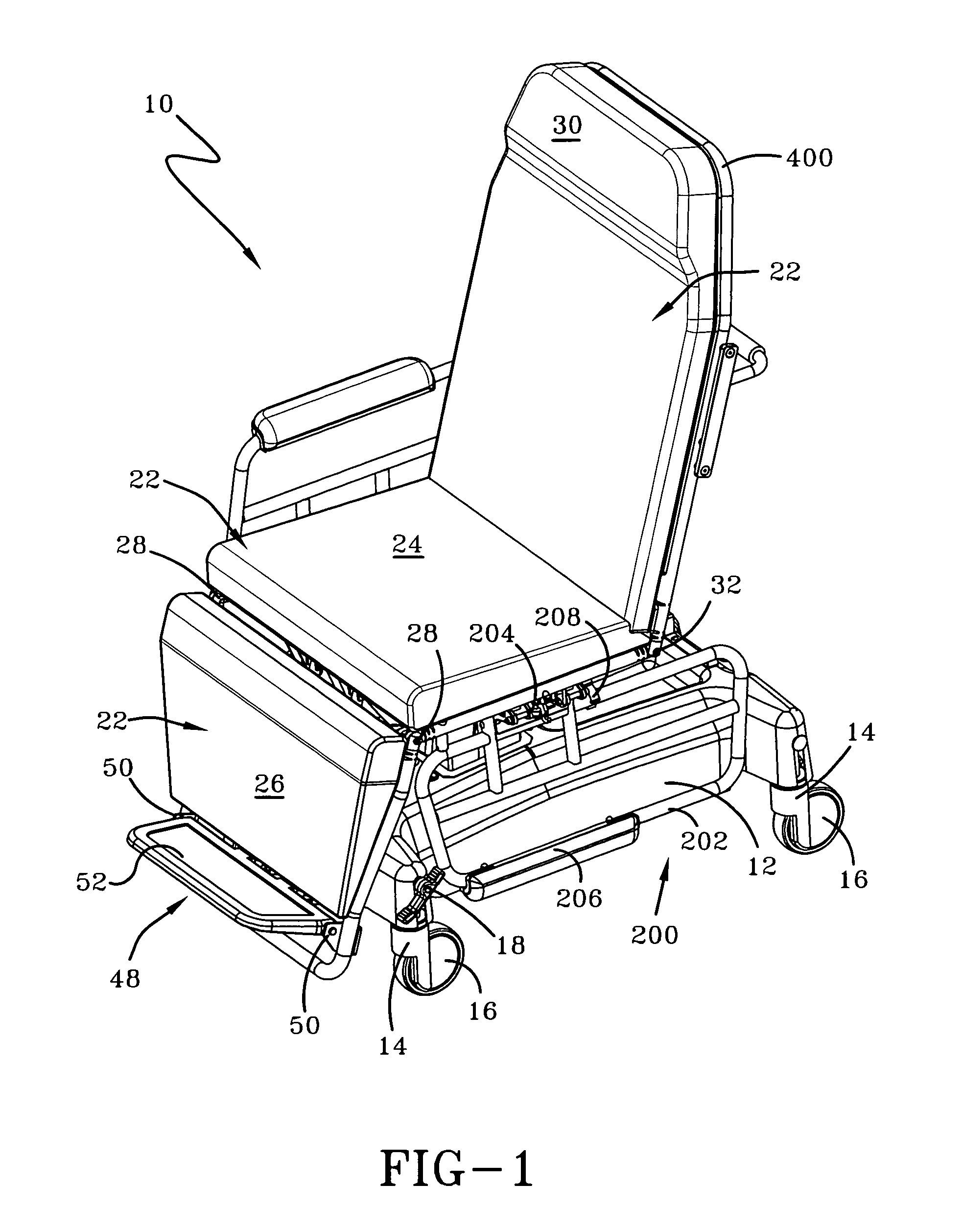
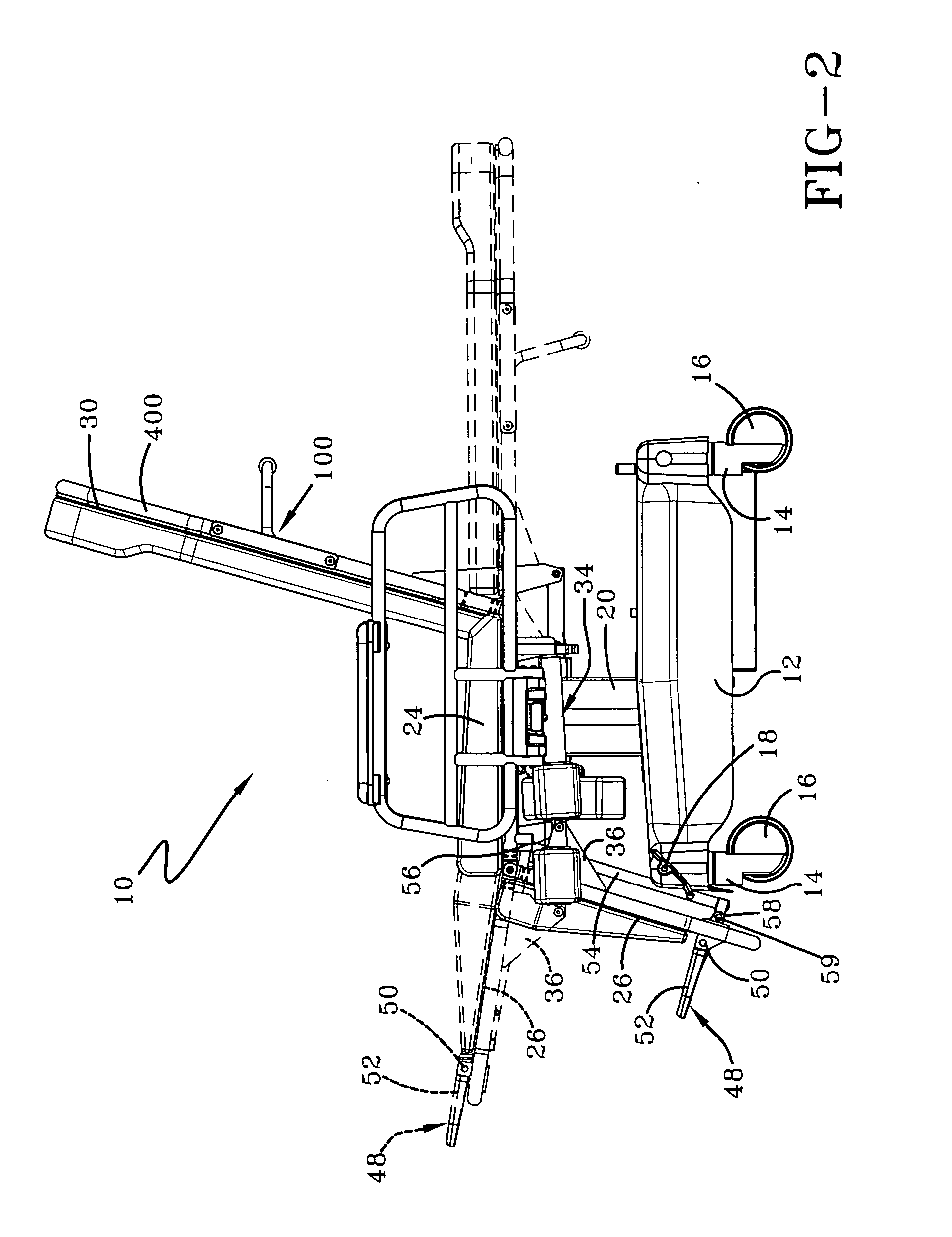
[0022] Referring now to FIGS. 1 and 2, a medical chair in accordance with this invention is designated generally by the numeral 10. Base 12 provides support for medical chair 10 and rides on a plurality of caster assemblies 14 and associated wheels 16 so that chair 10 is mobile. Central brake system 18 selectively controls the ability of the caster assemblies 14 to swivel and the ability of the wheels 16 to rotate and lock. Preferably, a four wheel brake and steer caster system is employed, such systems being generally known in the art.

[0023] Telescoping support column 20 extends upwardly from base 12 to support a patient support structure that is generally designated by the numeral 22. Patient support structure 22 includes various sections that may be positioned to provide a chair structure or stretcher structure or any compromise between these positions, as is generally known. Particularly, support column 20 supports seat section 24 generally parallel to the ground, and leg suppo...


PUM


Abstract

A medical chair provides a radiolucent backrest pivotally secured to a seat section. A pivoting push bar on the backrest pivots between an operative position, where it can be used to maneuver the chair, and a storage position where it does not compromise the radiolucent property of the backrest. The chair includes a leg support section, and the backrest and leg support section pivot between a chair structure and a stretcher structure. The pivoting of the backrest and legs support section are controlled by actuators that are positioned so as not to interfere with the radiolucent property of the backrest. A foot platform on the leg support section is connected to remain substantially parallel to the seat section as the leg support section is pivoted. A remote control allows for adjusting the configuration of the chair from points distant from the medical chair.

Description

TECHNICAL FIELD [0001] The present invention generally resides in the art of patient chairs and, more particularly, relates to a patient chair having features that make the chair particularly useful for radiographic and fluoroscopic procedures. BACKGROUND ART [0002] Mobile patient chairs are generally known in the art, and are used for patient transfer and transport, and, in some instances treatment and recovery, at medical facilities. They typically include a patient support structure that includes a seat section, a back rest, and a leg support section, wherein the back rest and leg support sections may be positioned relative to the seat section to provide a chair structure or stretcher structure, as needed. The support structure is generally carried on a base that rides on caster assemblies, which allow for transport of the patient chair. In these chairs, a patient can be quickly and safely moved from a sitting position to supine positions and vice versa. [0003] Certain medical ch...

Claims


Application Information

Patent Timeline
Patent Type & Authority Applications(United States)
IPC IPC(8): A61B6/04A61G5/00A61G5/10A61G7/015
CPCA61G5/006A61G5/1059A61G5/1072A61G7/015A61B6/548A61G2007/051A61G2007/0514A61G2007/0522A61G2203/12A61G7/0507A61G7/051A61G7/0514A61G7/0522
Inventor FAILOR, RAYMOND A.FOX, MICHAEL D.
Owner WINCO MFG
Learn More