
Aneurysm cover device for embolic delivery and retention

an aneurysm and embolic technology, applied in wound clamps, medical science, surgery, etc., can solve the problems of wide neck, large terminal aneurysms, and inability to coordinate the use of embolic delivery, and the potential utility of an implant suitable for coordinated use with embolic delivery has not been appreciated

Inactive Publication Date: 2011-06-16
TYCO HEALTHCARE GRP LP
View PDF4 Cites 96 Cited by
  • Summary
  • Abstract
  • Description
  • Claims
  • Application Information

AI Technical Summary

Benefits of technology

[0005]In addition, the devices and methods described herein can be used with other conventional aneurysm filler bodies such as embolic coils (e.g., platinum detachable, polymer or another configuration of coil), biological, biodegradable, or bioabsorble materials such as microfibrillar collagen, various polymeric beads and polyvinylalcohol foam. The polymeric agents may additionally be crosslinked, sometimes in-vivo, to extend the persistence of the agent at the vascular site or increase its ability to promote a desired biological response in the aneurysm such as embolization or endotheliazation.
[0008]The elongate shaft facilitates appropriate positioning of the cover at the neck by using the embolic delivery catheter that is placed within the shaft as a guide for positioning the cover connected to the shaft (actually, in the case of a preferred briad construction—integreally formed). This feature is particularly useful for addressing coverage of wide-neck aneurysms, and aneurysms having irregular shaped openings in which placement may be all the more difficult—especially win an unstablized implant.
[0012]Even if not intended for use as a flow disrupter, a relatively tighter braid matrix in the cover may offer an excellent matrix for tissue growth. When fully endothelialized across the neck, the aneurysm is cured. The subject implant can help promote such outcome due to the known tendency of adequately tight wire braid surfaces to promote proximal tissue endothelization.
[0013]Employing a braid of sufficient wire count to offer density for flow disruption and / or endotheliazation also provides some gross structural benefits. Namely, with higher wire counts in the cover (e.g., by employing one or more layers adding up to about 96 wire count, and more preferably about 144, 192 or higher, the cover takes on the shape of a substantially circular periphery (whether set flat as a disc or cupped in shape). As compared to structures having lesser wire counts that merely resemble flower petals, the full circular periphery provides both a better barrier to embolic extravasation, and a continuous / uniform fit with curvilinear vascular anatomy in opposition thereto. The clear benefits imparted to the treatment of the aneurysm by this configuration are better overall aneurysm seal and / or more complete endothelization across the neck of the aneurysm into adjacent tissue.
[0015]In some variations, the invention includes an implant and embolic delivery catheter configured to function as noted above, wherein the embolic delivery catheter is releasably retained within the shaft by a slip fit. A slightly tighter loose interference fit may, likewise, be employed. In either case, an abutment feature will be provided at the distal end of the implant shaft (e.g., a platinum marker band) so the delivery catheter can function effectively as a pusher during implant placement.
[0020]Systems for treating aneurysms include the implant mounted on the catheter that delivers the embolic materials, and the embolic materials that are delivered. Methods of treating aneurysms include positioning the implant mounted over the embolic delivery catheter at the aneurysm, and delivering the embolic materials. Removal of the delivery catheter may be accomplished by simple withdrawal or by breaking of an interface with the braid, such as provided with threads on the catheter so that it can be unscrewed from the elongate shaft.

Problems solved by technology

These and other terminal aneurysms often grow large and have wide necks due to the direct path of blood pounding into the vascular malformation.
Their stated purpose and function is merely temporary in nature, and the potential utility of an implant suitable for coordinated use with embolic delivery has not been appreciated.

Method used


Image

  • Aneurysm cover device for embolic delivery and retention
  • Aneurysm cover device for embolic delivery and retention
  • Aneurysm cover device for embolic delivery and retention

Examples


Embodiment Construction

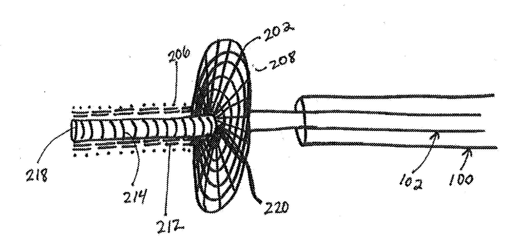
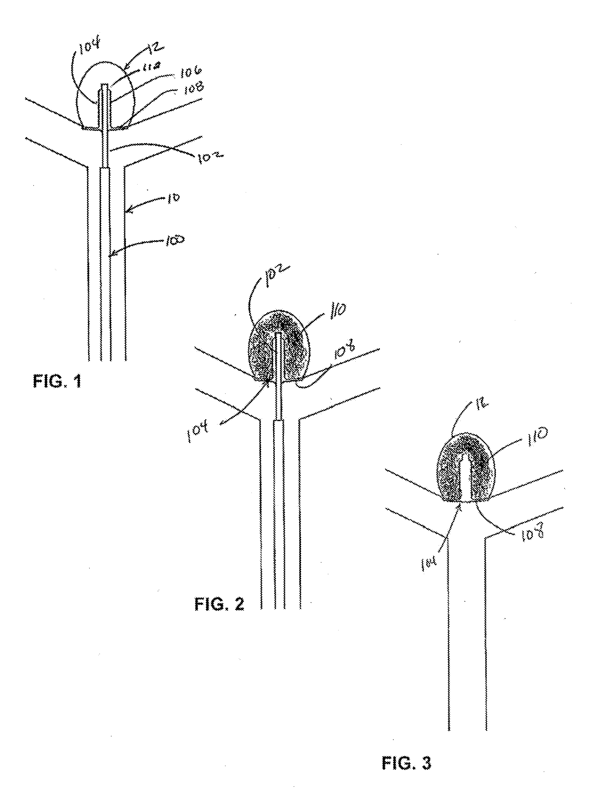
[0027]Turning now to FIG. 1 a catheter 100 is advanced within the vasculature 10 to the site of an aneurysm 12. Typically, a catheter or a microcatheter is initially steered into or adjacent to the entrance of an aneurysm, often aided by the use of a steerable guidewire. The wire is then withdrawn from the microcatheter lumen to allow delivery of the subject implant and / or system

[0028]A distal end of a core member 102 is located within the entrance of the aneurysm 12. The core member includes a lumen (not shown) and implant 104 (e.g. the combination of the braided shaft and braided cover) releasably set or mounted thereon. Naturally, delivery or guide catheter 100 can be positioned within the aneurysm 12 and then withdrawn while leaving the core member 102 and implant 104 within the aneurysm 12. Alternatively, the implant 104 and core member 102 can be advanced from catheter 100 into the aneurysm.

[0029]In variations where catheter 100 is retracted to expose the implant, the implant ...


PUM


Abstract

An implant for treating brain aneurysms, especially terminal aneurysms, comprises a neck cover and elongate shaft removably secured to an embolic delivery catheter. As such, the shaft aids in directing and placing the cover at the aneurysm neck, protecting the delivery catheter from adhesion with the embolic material, and securing the cover in place with connection or adhesion of the shaft to the embolic material delivered through the catheter. The implant can be anchored at the aneurysm either by interface and / or adhesion of the shaft or shaft and cover with the resident embolic materials.

Description

BACKGROUND OF THE INVENTION[0001]Numerous treatment strategies and devices have been devised to better treat brain aneurysms located at vessel bifurcation locations. These and other terminal aneurysms often grow large and have wide necks due to the direct path of blood pounding into the vascular malformation.[0002]In effort to more effectively treat such aneurysms, U.S. Pat. No. 6,344,048 to Chin discloses a temporary cover made of braid that is manipulated at attachment points on each end of the braid to expand and cover the neck of an aneurysm while embolic material (liquid or coils) are delivered thereto. U.S. Pat. No. 6,746,468 to Septka at FIG. 56 described another temporary cover to assist in holding coils or liquid embolic within terminal aneurysms.[0003]Neither device can function (or be reasonably modified to function) as a permanent implant. Their stated purpose and function is merely temporary in nature, and the potential utility of an implant suitable for coordinated use...

Claims


Application Information

Patent Timeline
IPC IPC(8): A61B17/08
CPCA61B17/12022A61B17/12113A61B2017/12095A61B2017/12054A61B17/12172
Inventor BECKING, FRANK P.ROSQUETA, ARTURODIECK, MARTIN S.ABOYTES, MARIADEBEER, NICHOLAS C.FIRESTONE, LEIGH
Owner TYCO HEALTHCARE GRP LP
Learn More