
Electromagnetic stapler with a manually adjustable depth adjuster
a technology of electric power and depth adjuster, which is applied in the field of electrical power and stapler, can solve the problems of not having a stapler that allows at least one adjustable adjustmen
- Summary
- Abstract
- Description
- Claims
- Application Information
AI Technical Summary
Problems solved by technology
Method used
Image

Examples
Embodiment Construction
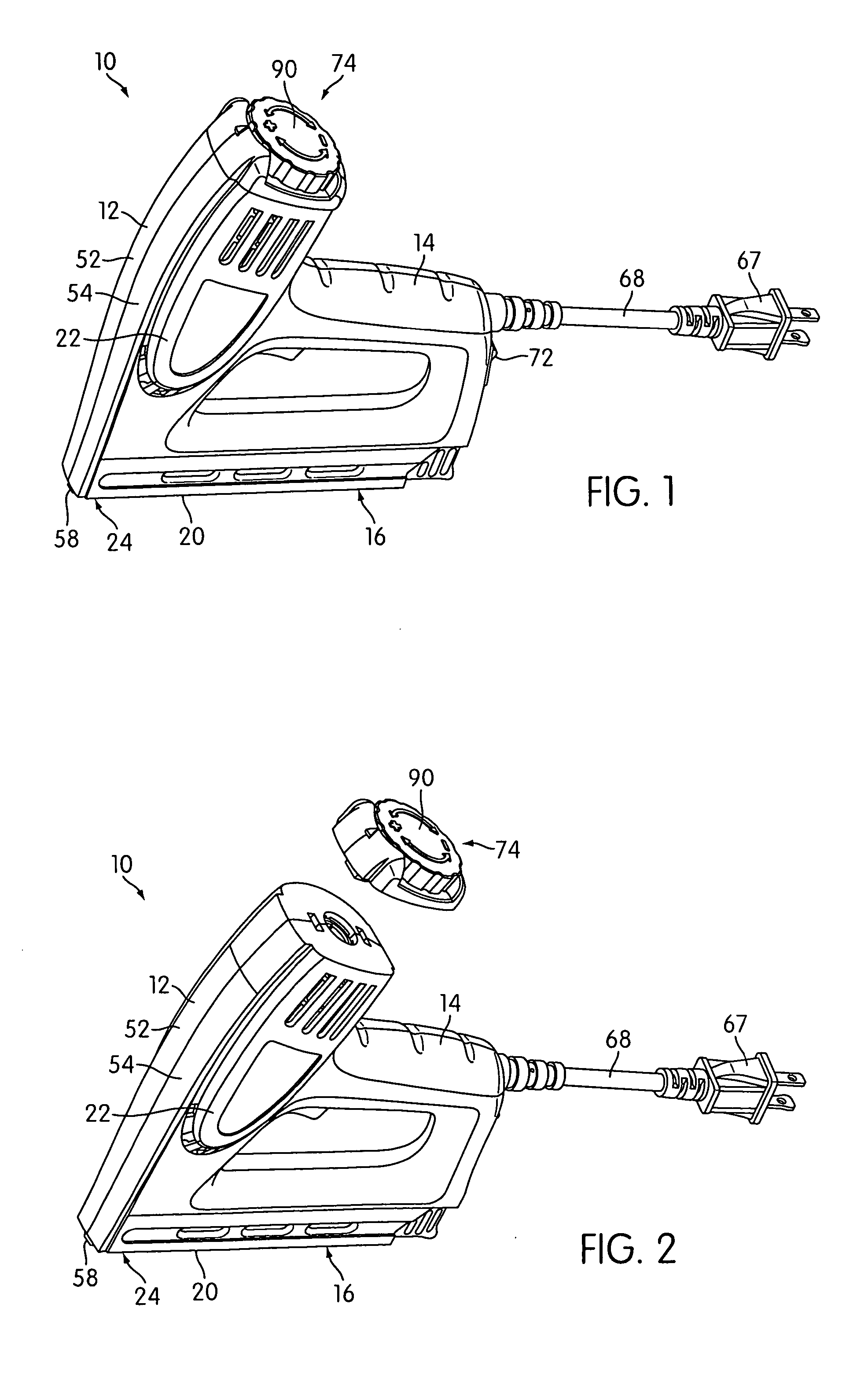
[0022]FIG. 1 shows a stapler 10 according to at least one embodiment of the present invention. The stapler 10 includes a housing 12 that is configured to be carried by a user via a handle portion 14 of the housing 12. Connected to, or integral with, the housing 12 is a magazine 16 for carrying a supply of fasteners 18 to be driven into a workpiece (not shown). The magazine 16 includes a substantially flat bottom surface 20 that is configured to be placed on the workpiece. The housing 12 also includes a body portion 22 that extends upwardly from a forward end 24 of the magazine 16 so as to define a drive track 25 (shown in FIGS. 4-7).
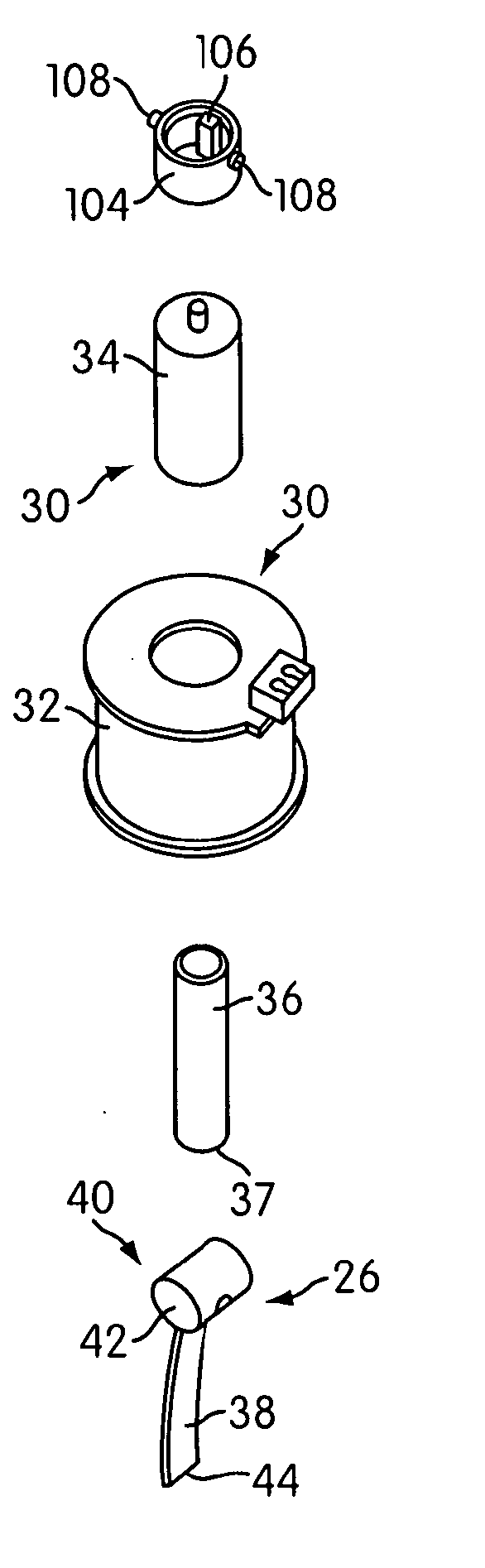
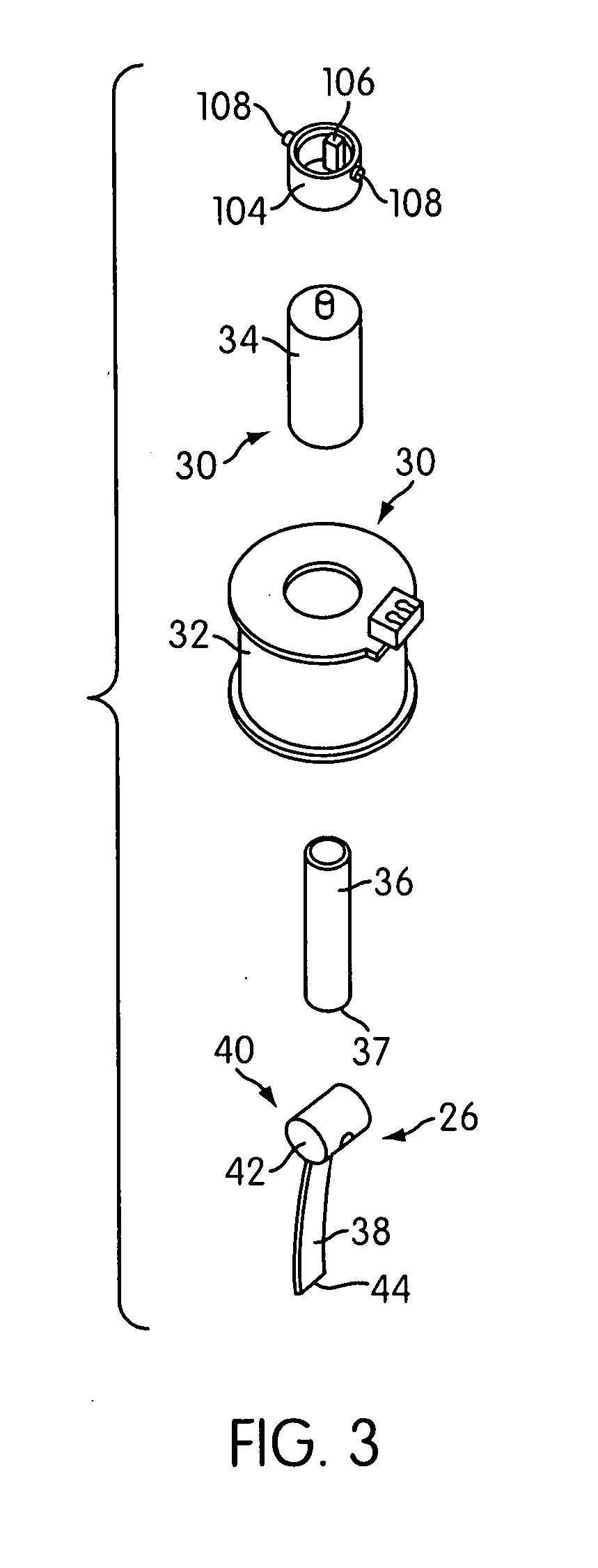
[0023] As shown in FIGS. 5-7, a driver 26 that is configured to drive the fasteners 18 out of the drive track 25 and into the workpiece is disposed within the body portion 22 of the housing 12. The driver 26 is constructed and arranged to be reciprocally moveable within the housing 12 so as to drive successive fasteners 18 from the magazine 16 into the ...
PUM
 Abstract
Description
Claims
Application Information