Pivoting tacker

a technology of tacks and tacks, applied in the field of tacks, can solve the problems of severe limitations in the number of tacks that the magazine can hold

Inactive Publication Date: 2010-01-07
EASYLAP LTD
View PDF21 Cites 158 Cited by
  • Summary
  • Abstract
  • Description
  • Claims
  • Application Information

AI Technical Summary

Benefits of technology

[0012]There is also provided in accordance with an embodiment of the present invention a method for applying a rotary tack, including providing a drive shaft coupled to a trigger, wherein operating the trigger causes rotation of the drive shaft, a magazine that holds a rotary tack rotatingly connected to the drive shaft, and an articulated applicator arm including a rotatable output shaft rotating

Problems solved by technology

It has been found that in many applications the length of the device distal to the pivot m

Method used


Image

  • Pivoting tacker
  • Pivoting tacker
  • Pivoting tacker

Examples


Embodiment Construction

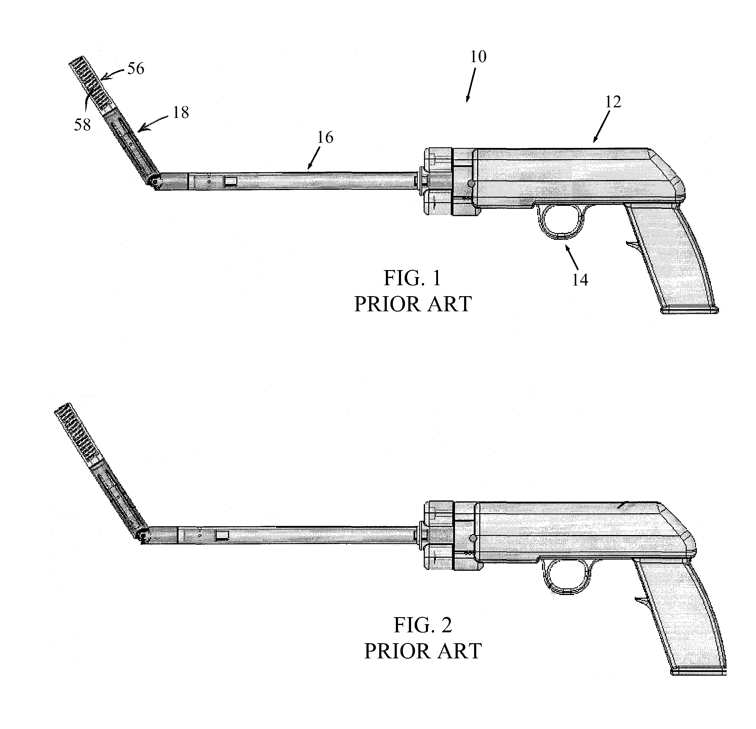
[0022]Reference is now made to FIGS. 1 and 2, which illustrates a tacker 10 of the prior art (US Patent Application 12 / 02224).

[0023]Tacker 10 may include a handle 12 with a trigger assembly 14. A drive shaft 16 is coupled to trigger assembly 14. An articulated applicator arm 18 is pivotally connected to drive shaft 16 at a pivot 34. A magazine 56 holds rotary tacks 58 and is positioned distal to pivot 34 (FIG. 2).

[0024]A proximal end 20 (FIG. 2) of drive shaft 16 is splined (or otherwise suitably shaped) for mating with a drive assembly (not shown) of trigger assembly 14. The proximal end 20 of drive shaft 16 is journaled in a roller bearing housing 22 (FIG. 2). Drive shaft 16 extends through an extension tube (also called housing) 24. Upon operation of trigger assembly 14, the drive assembly turns drive shaft 16 about a longitudinal axis 32 thereof (FIG. 2), and causes deployment of tack 58 from magazine 56.

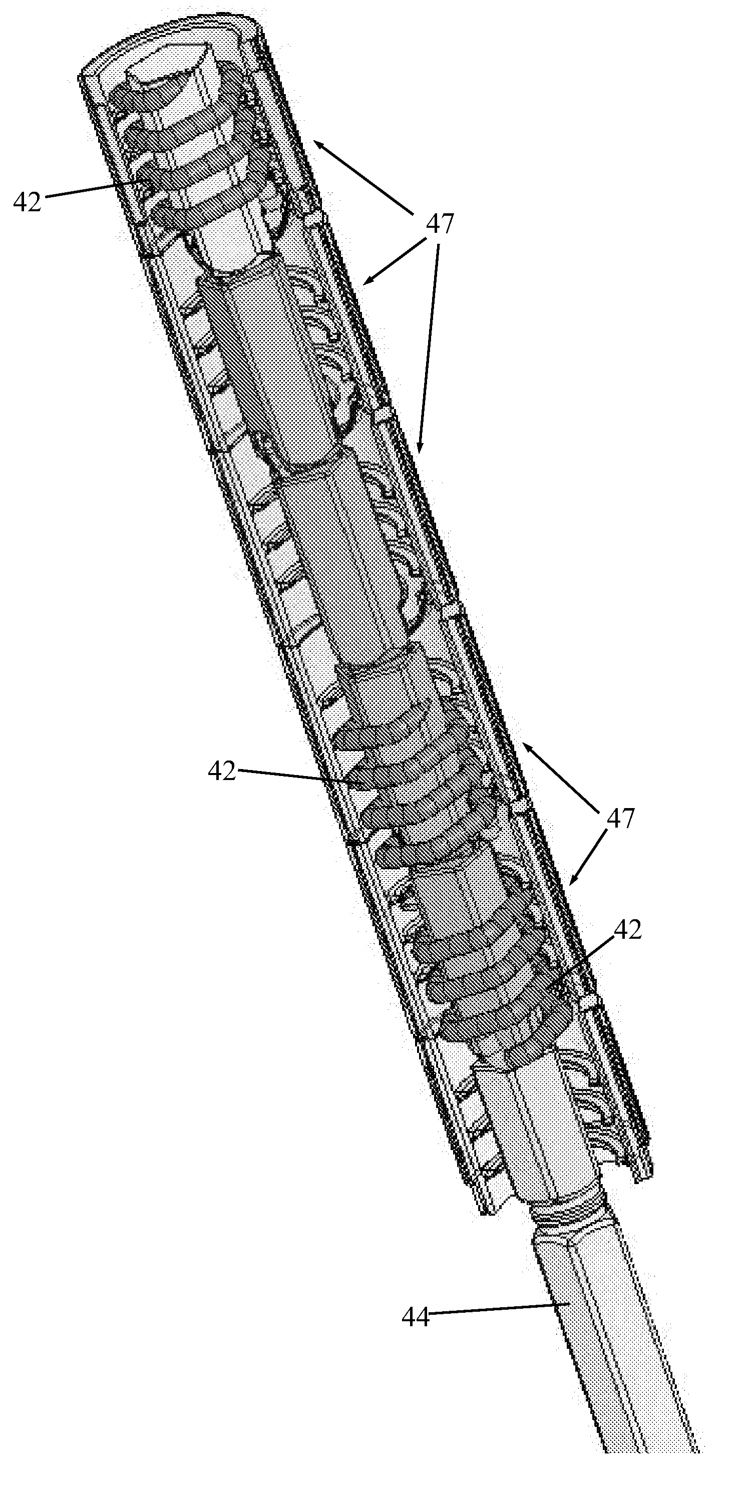
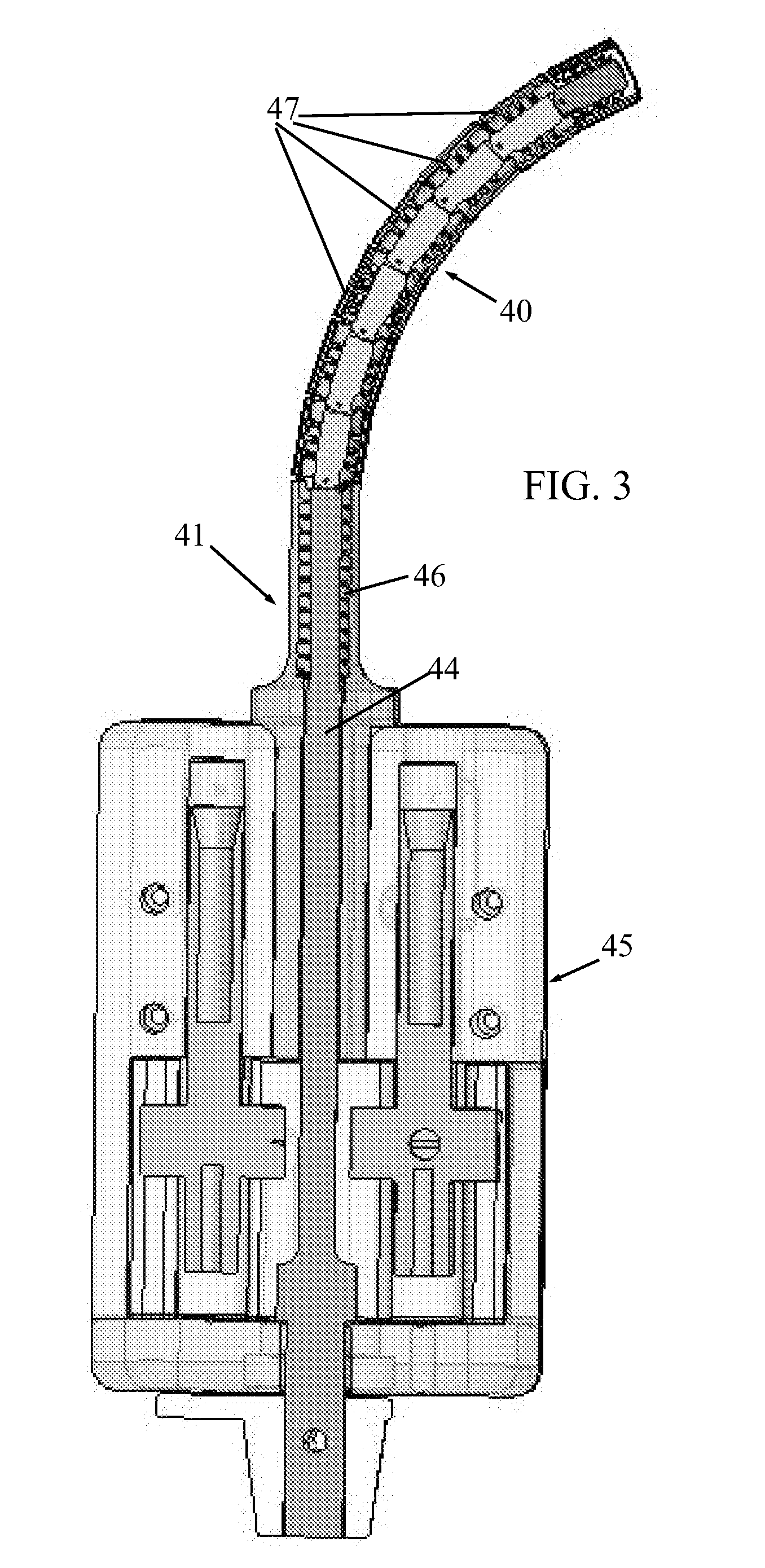
[0025]Reference is now made to FIGS. 3-6, which illustrate an articulated a...


PUM

PropertyMeasurementUnit
Thicknessaaaaaaaaaa
Shapeaaaaaaaaaa

Abstract

A tacker for applying a rotary tack, including a drive shaft coupled to a trigger, wherein operating the trigger causes rotation of the drive shaft, a magazine that holds a rotary tack rotatingly connected to the drive shaft, and an articulated applicator arm including a rotatable output shaft rotatingly connected to the magazine, wherein the magazine is proximal to the articulated applicator arm, the articulated applicator arm including one or more pivoting links, each pivoting link including a link shaft, wherein operation of the trigger causes the driver shaft and the one or more link shafts to rotate so as to distally advance the rotary tack from the magazine past the one or more pivoting links.

Description

FIELD OF THE INVENTION[0001]The present invention relates generally to devices and methods for applying surgical fasteners, such as rotary tacks, to tissues, such as for hernia repairs and the like, and particularly to such devices and methods for use in laparoscopic and endoscopic procedures, wherein the tacks pass through pivoting structure.BACKGROUND OF THE INVENTION[0002]A number of surgical procedures require instruments that are capable of applying a surgical fastener to tissue in order to form tissue connections or to secure objects to tissue. For example, during hernia repair it is often desirable to fasten a surgical mesh to the underlying body tissue. In laparoscopic procedures, such as for hernia repair, surgery is performed in the abdomen through a small incision, while in endoscopic procedures surgery is performed through narrow endoscopic tubes inserted through small incisions in the body. Laparoscopic and endoscopic procedures generally require long and narrow instrum...

Claims


Application Information

Patent Timeline
IPC IPC(8): A61B17/04A61B17/00
CPCA61B17/064A61B17/068Y10T29/49833A61B2017/2905A61B2017/0649
Inventor LEVIN, SHALOMALTMAN, NIR
Owner EASYLAP LTD
Why Eureka
Try Eureka