Method and apparatus for surgical clamping

a clamping and breastbone technology, applied in the field of clamping, can solve the problems of not being able to achieve the highest conceivable stability, not being able to achieve the effect of a clamp, and being unable to achieve a symmetrical and especially a flat bearing surface of the clamp, so as to achieve good locking, reduce the resistance of the clamping halves to move, and achieve the effect of high resistance to their movement away

Inactive Publication Date: 2009-05-14
MAX HAUSER SUDDEUTE CHIRURGIEMECHANIK +1
View PDF10 Cites 159 Cited by
  • Summary
  • Abstract
  • Description
  • Claims
  • Application Information

AI Technical Summary

Benefits of technology

[0021]As an additional aspect of the present invention an especially good locking can be achieved when the toothing of the respective toothed rods is configured such that the flanks belonging to each tooth run in the same direction, looking from the base of the tooth to the tip of the tooth; thus, for example, both flanks run from bottom left to upper right. Thanks to this flank geometry, the two toothed rods are pulled together in the transverse direction when there is a tensile stress in the lengthwise direction. An especially advantageous aspect of the present invention is to provide a profile as a shark fin profile, since it presents an especially low resistance to the moving of the clamp halves toward each other and an especially high resistance to their moving away from each other.
[0022]As an additional aspect of the present invention, an at least partly especially intimate and thus especially effective contact between toothings is achieved by providing that at least one of the toothed rods has a curvature along its lengthwise dimension wherein the toothing is directed toward the midpoint of the curvature or away from the midpoint of the curvature. This effect is further strengthened when both toothed rods have a curvature along their lengthwise dimension, wherein the toothing is directed toward the midpoint of the curvature or away from the midpoint of the curvature and the curvatures are opposite to each other. The mutually opposing curvatures in this case can be convex or concave.
[0023]As an additional aspect of the present invention, one improvement increases the stability of the surgical clamp on the bone if the surfaces of the left clamp half and / or the right clamp half that make contact with the bone have a structurization, preferably a tooth structure.

Problems solved by technology

However, in a number of problem patients, such as those with a strong chronic cough, there are complications due to the fact that the thread is exposed to strong stress and will break.
However, all these clamps have a number of disadvantages in common: it is not possible to achieve a symmetrical and especially a flat bearing surface of the clamp with them.
Thus, the primary effect achievable with a clamp, that of a two-dimensional pressure, as opposed to the uni-dimensional pressing of a thread, is thwarted in that the effective bearing surface is ultimately confined to the region of the sleeve.
In another common disadvantage, the fixation mechanism only acts locally in a small region of the clamp and is therefore still always exposed to a certain degree of wobbling and tilting and does not achieve the highest conceivable stability.
As a third common disadvantage, when tightening the clamp, it is a problem that the relative movement of the halves of the clamp toward each other still occurs only by the movement of one half of the clamp, and so the tightening is necessarily asymmetrical, which can result in a fourth common disadvantage, namely the halves of the breastbone not being fixed in the optimal position relative to each other.

Method used


Image

  • Method and apparatus for surgical clamping
  • Method and apparatus for surgical clamping
  • Method and apparatus for surgical clamping

Examples


Embodiment Construction

[0037]Reference will now be made in detail to several embodiments of the invention that are illustrated in the accompanying drawings. Wherever possible, same or similar reference numerals are used in the drawings and the description to refer to the same or like parts or steps. The drawings are in simplified form and are not to precise scale. For purposes of convenience and clarity only, directional terms, such as top, bottom, up, down, over, above, and below may be used with respect to the drawings. These and similar directional terms should not be construed to limit the scope of the invention in any manner. The words “connect,”“couple,” and similar terms with their inflectional morphemes do not necessarily denote direct and immediate connections, but also include connections through mediate elements or devices.

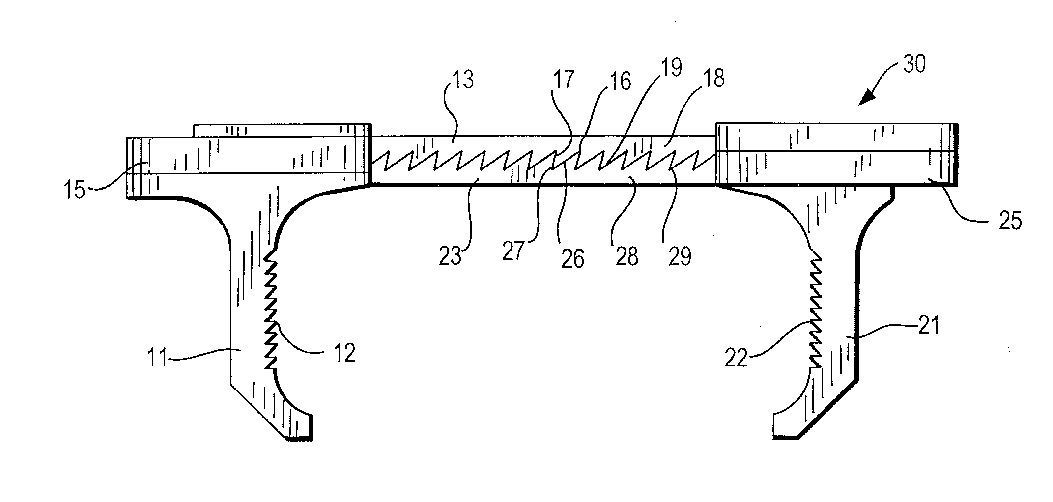
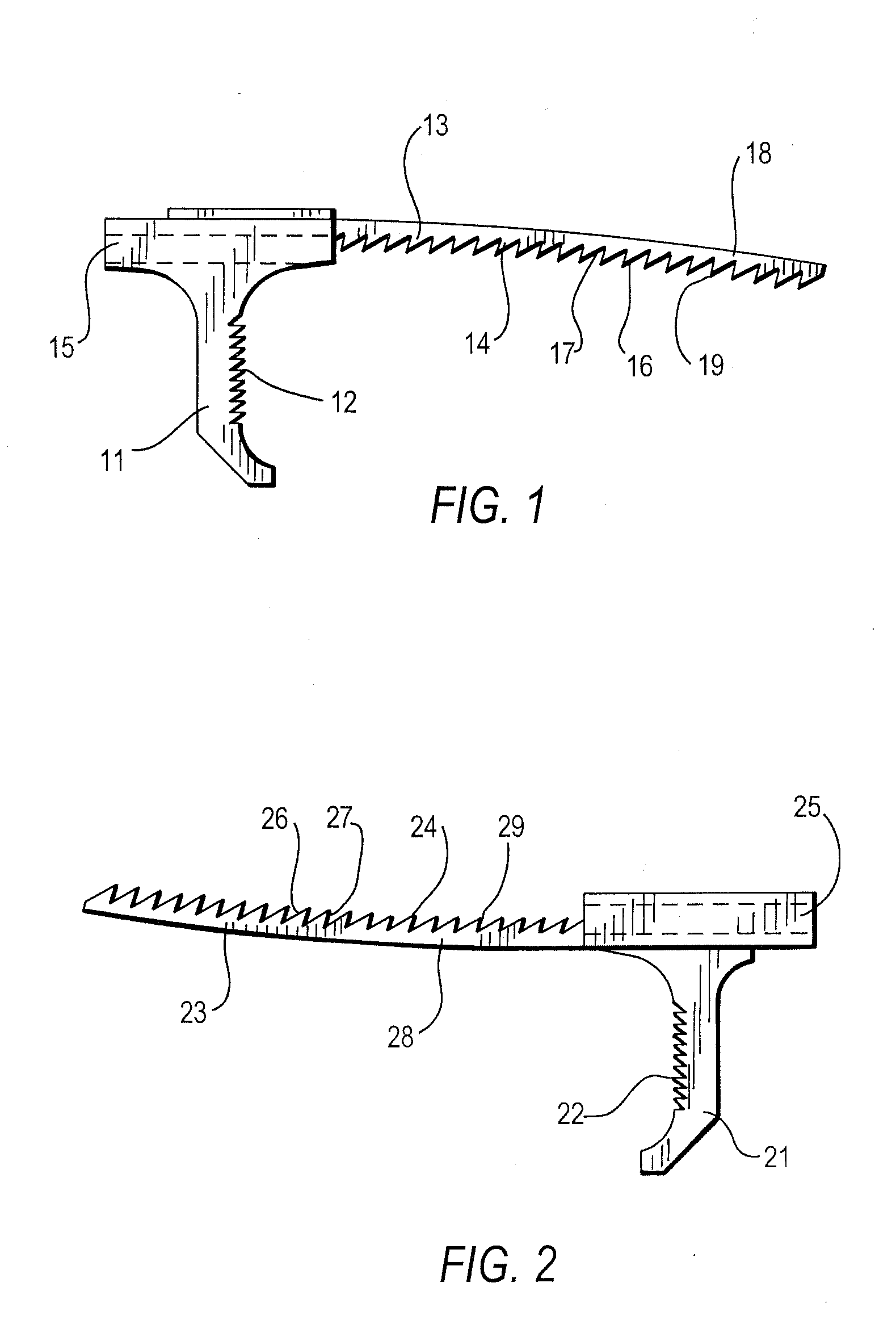
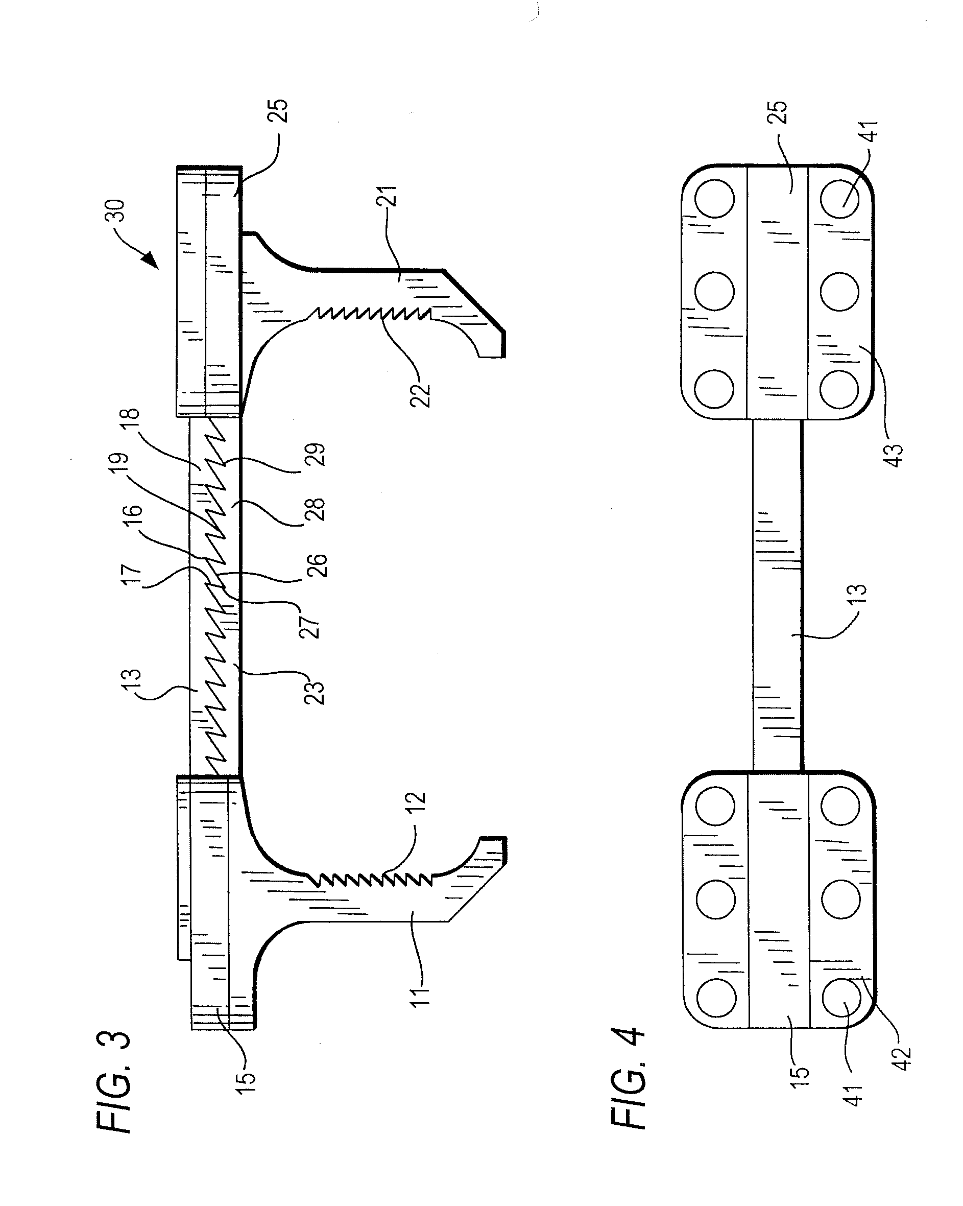
[0038]FIG. 1 shows a right clamp half 11 of a surgical clamp with a housing 15 and a first toothed rod 13, arranged in the housing 15, and a toothing 14. The first toothed ro...


PUM


Abstract

The invention concerns a clamp, especially a surgical clamp, with a left clamp half to receive a left half of a breastbone during a surgical procedure, a right clamp half to receive a right half of the breastbone, as well as a first toothed rod and a detent mechanism engaging in the first toothed rod to secure the left clamp half at a distance from the right clamp half, wherein the detent mechanism engaging in the first toothed rod has a detent region extending at least from the left clamp half to the right clamp half.

Description

CROSS REFERENCE TO RELATED APPLICATIONS[0001]This application relates to and claims priority from DE 10 2007 052 315.9, filed Oct. 31, 2007, the entire contents of which are herein incorporated fully by reference.FIGURE SELECTED FOR PUBLICATION[0002]FIG. 3.BACKGROUND OF THE INVENTION[0003]1. Field of the Invention[0004]The present invention relates to a clamp. More specifically, the present invention relates to a surgical breastbone clamp containing a detent mechanism extending between respective opposing clamp halves.[0005]2. Description of the Related Art[0006]The related art involves the performing of medical operations on the open rib cage, such as heart operations. These operations have almost become a routine procedure, one which is often done. In order to open the rib cage, one generally saws the breastbone (sternum) lengthwise, making it possible to spread the ribs apart and work freely in / on the open chest.[0007]After the operation, the chest has to be closed again. In part...

Claims


Application Information

Patent Timeline
Patent Type & Authority Applications(United States)
IPC IPC(8): A61B17/04
CPCA61B17/823Y10T24/44624Y10T24/44034
Inventor REHM, WALTER
Owner MAX HAUSER SUDDEUTE CHIRURGIEMECHANIK
Why Eureka
Try Eureka