
Cover device for a power tool

Inactive Publication Date: 2006-03-30
HILTI AG
View PDF10 Cites 41 Cited by
  • Summary
  • Abstract
  • Description
  • Claims
  • Application Information

AI Technical Summary

Benefits of technology

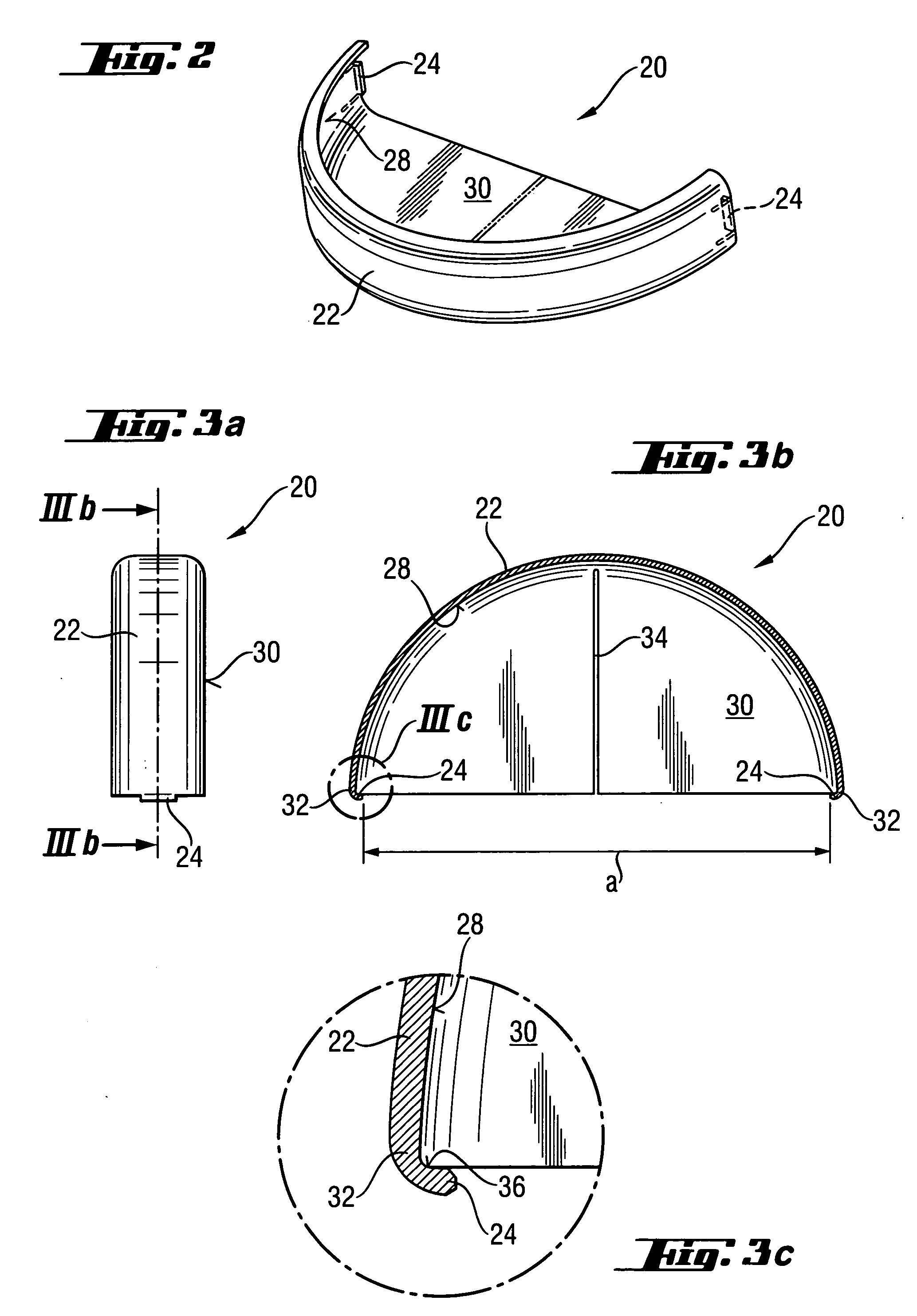
[0013] The engaging-from-behind elements provide for a particularly easy locking of the cover device with matching locking means, with the distance between the engaging-from-behind elements being increased by application of corresponding external forces. When the cover device is mounted on the power tool, it can easily be pinned on the shielding member, with the distance between the engaging-from-behind elements assuming its initial value upon removal of external forces as a result of action of restoring forces which return the at least one engaging-from-behind element to its initial position. Upon the distance between the engaging-from-behind element returning to its initial value, they become locked with the matching locking means of the power tool. Upon release of the cover device, the engaging-from-behind elements are displaced away from each other against the restoring force in order to break the locking between the engaging-from-behind elements and the matching locking means.
[0014] According to a particular advantageous embodiment of the present invention, the engaging-from-behind elements extend radially inward from tangential limiting edges of the bearing surface of the bearing means. Thereby, formation of specific matching means, e.g., in form of grooves or bores, on the shielding member can be avoided, which minimizes manufacturing costs. In addition, the cover device can be easily and rapidly pinned on the power tool, with the engaging-from-behind elements engaging from behind the limiting edges of the shielding member, securing the cover device in both tangentional directions.
[0015] Advantageously, the at least on of the engaging-from-behind elements is formed as a hook-shaped element securely connected with the bearing means. In addition, the protective disc is provided with a substantially radially extending slot. The slot gives the cover device a certain elasticity, providing for displacement of the engaging-from-behind elements away from each other under action of external forces, with the elements being returned to their initial position under the action of restoring forces. This makes possible an easy mounting of the cover device on the power tool and dismounting it therefrom without use of any assembly or other tools.
[0019] Advantageously, the engaging-from-behind elements are formed integrally with the remaining part of the cover device as a one-piece part, i.e., by deformation or partial removal of the material that forms the cover device. Thereby, manufacturing costs are reduced, and a stable locking element is produced.
[0020] Advantageously, the protective disc extends at least over a half-circle defined by the bearing means. Thereby, the working tool can be covered particularly well in order to protect the user from flying sparks and similar released and accelerated particles. Easy mounting and dismounting of the cover device also insure a rapid replacement of the working tool.

Problems solved by technology

However, the manufacturing costs of the device of DE 94 03 777 are relatively high.
In addition, the means that provides for the forcelocking connection of the cover device on the power tool, such as, e.g., clamp screws, are either tedious to operate or are not capable to absorb forces acting on the cover device during the power tool operation, such as, e.g., tangentially acting impacts, without the cover device being displaced.

Method used


Image

  • Cover device for a power tool
  • Cover device for a power tool
  • Cover device for a power tool

Examples


first embodiment

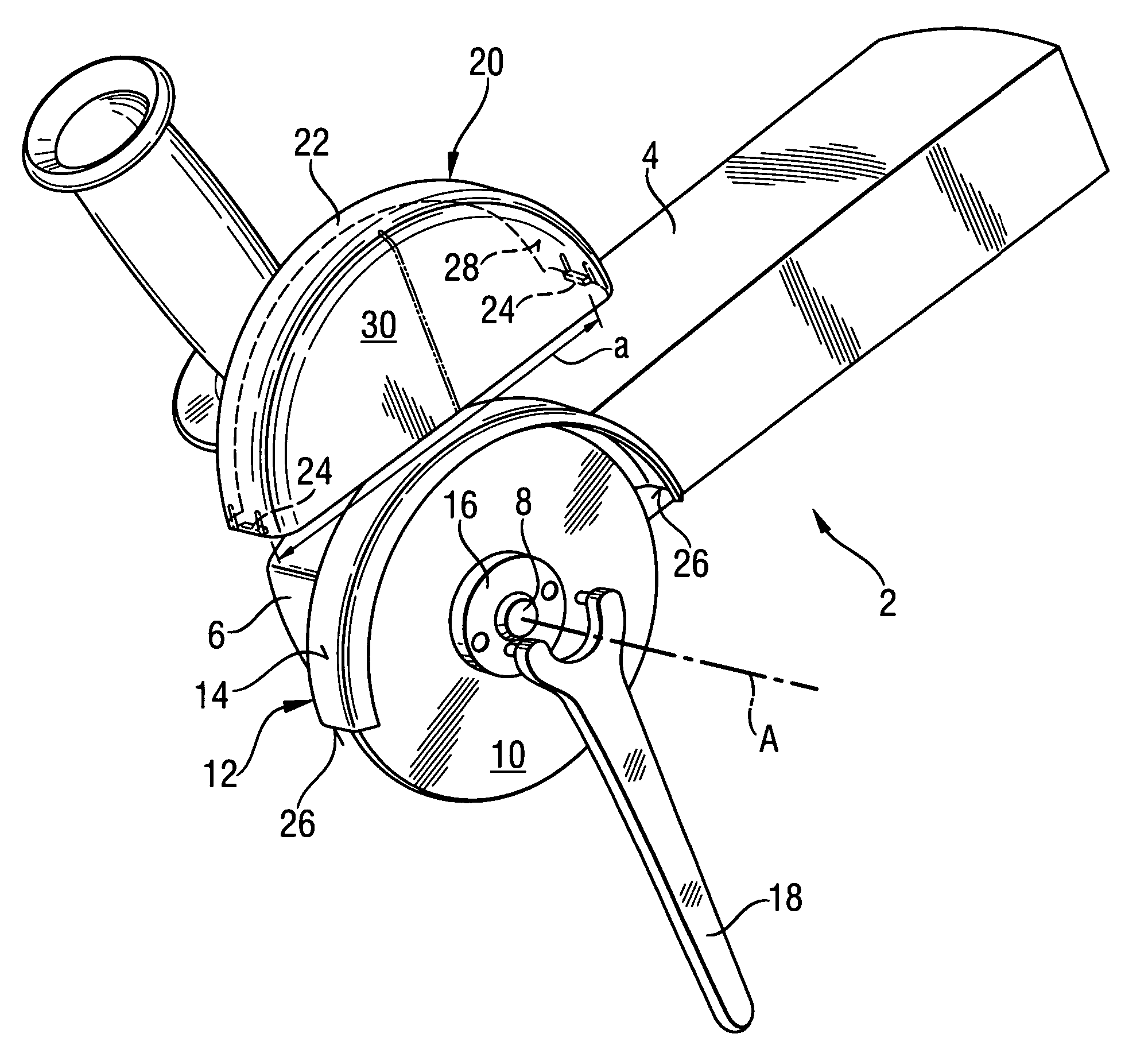
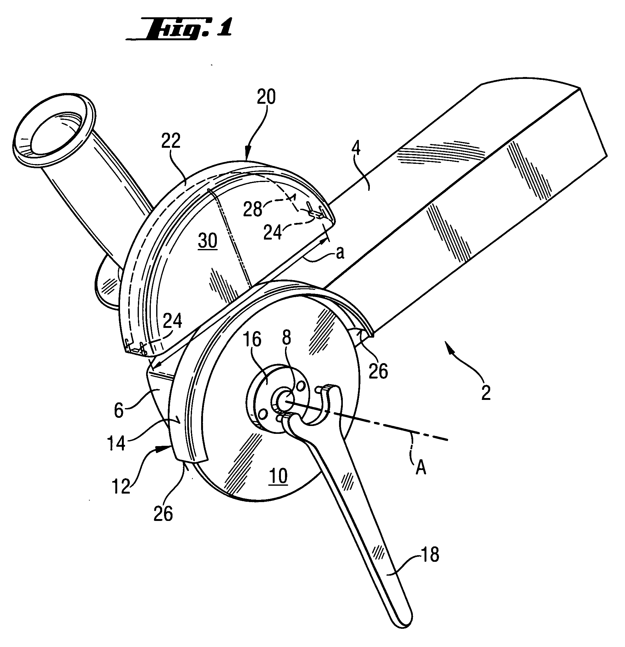
[0036]FIGS. 3a-3c shows the engaging-from-behind elements 24. The elements 24 have, at their respective free ends, two hook-shaped elements 32 which are formed at the tangential ends of the bearing means 22. The hook-shaped elements 32, together with the engaging-from-behind elements 24, are formed, together with the bearing means 22, as a substantially formstable single piece. In order to be able to displace the engaging-from-behind elements 24 away from each other to increase the distance a therebetween for hooking the cover device 20 on the limiting edges 26 of the shielding member 12 and for removing the cover device 20 off the shielding member 12, there is formed, in the protective disc 30, a radial slot 34. The slot 34 permits to deform, the bearing means 22 during mounting of the cover device 20 on the shielding member 12 and dismounting of the cover device 20 from the shielding member 12. The slot 34 provides for a radial pivotal movement of the engaging-from-behind elements...

second embodiment

[0038]FIGS. 4a-4c show an alternative, second embodiment of the engaging-from-behind elements 24. According to this embodiment, the engaging-from-behind elements 24 are formed on a locking nose 38 of an elastically resilient locking element 40. The locking element 40 has a spring arm 42 that is formed by two tangentional, extending parallel to each other, cut-ins 44 provided at respective tangential ends of the bearing means 22. The cut-ins 44 provide for elastic pivotal movement of the engaging-from-behind elements 24 in the radial direction relative to the bearing means 22 in order to change the distance a therebetween.

[0039] With both embodiments of the engaging-from-behind elements 24, the cover device 20 can be rapidly pinned on the shielding member 12, without using any additional tools.

[0040] In both embodiments, the engaging-from-behind elements 24 engage the limiting edges 26 in order to secure the cover device 20 on the shielding member 12 in the tangential and radial dir...


PUM


Abstract

A cover device for partially covering a front, in an axial direction, side of a disc-shaped working tool (10) of a power tool includes a bearing element (22) securable on the shielding member (12), which partially radially covers the working tool (10), and having a bearing surface (28) abutting, at least regionwise, an outer surface (14) of the shielding member (12), a protective disc (30) extending substantially transverse to the bearing surface (28) of the bearing means (22), and engaging-from-behind elements (24) provided at opposite tangential ends of the bearing surface (28), respectively, with at least one of the engaging-from-behind elements (24) being elastically pivotal in a radial direction.

Description

BACKGROUND OF THE INVENTION [0001] 1. Field of the Invention [0002] The present invention relates to a cover device for partially covering a front, in an axial direction, side of a disc-shaped grinding or separating tool of a power tool, in particular, of an angle grinder. The cover device is designed in particular to be retrofitted on the power tool. The cover device is provided with a bearing member having a bearing surface securable, when required, over a shielding member that partially covers the working tool. The bearing surface at least regionwise abuts the outer surface of the strip-shaped shielding member. The cover device also includes a protective disc which extends substantially transverse to the bearing surface and which partially covers the front, in the axial direction, side of the working tool. [0003] 2. Description of the Prior Art [0004] Most of angle grinders are equipped, standardwise, with a shielding member which is formed as a protective plate having an acruate...

Claims


Application Information

Patent Timeline
IPC IPC(8): B24B55/04
CPCB24B55/052
Inventor KOSCHEL, CHRISTIANFUNK, ALEXANDER
Owner HILTI AG
Learn More