Snow-shoveling apparatus

a technology of snowshoves and shovels, which is applied in the field of snowshoves, can solve the problems of not being very effective, convenient to use, and becoming quite costly, and achieve the effect of effectively removing snow

Inactive Publication Date: 2007-12-11
PURVIS RICHARD A
View PDF27 Cites 40 Cited by
  • Summary
  • Abstract
  • Description
  • Claims
  • Application Information

AI Technical Summary

Benefits of technology

[0015]Preferably, a first deformably resilient spring member is intercalated within the sleeve and operably fastened to the cable adjacent to the controller and a second deformably resilient spring member is nested within the distal end portion of the shaft. A plurality of interlocked pins are operably coupled to the cable and the distal end portion of the shaft. A release lever is pivotally connected to the shaft and is movable between raised and lowered positions. The first and second spring members cooperate with the pins for positioning the cable between tensed and equilibrium states when the operator disengages the controller so that the plow section can conveniently be locked at alternately displaced angles offset from the shaft.
[0016]A mechanism is included for automatically biasing the plow section to an equilibrium position after the plow section is biased to a pivoted position. Such an automatic biasing mechanism cooperates with the pivoting mechanism in such a manner that an operator can advantageously effectively remove snow from a ground surface while propelling the apparatus in a forward and substantially horizontal direction.

Problems solved by technology

Unfortunately, shovels of this type of design are not very effective and convenient to use.
For this reason, many elderly and physically disabled persons are unable to do this chore themselves, and must hire snow removers, which can become quite costly.

Method used


Image

  • Snow-shoveling apparatus
  • Snow-shoveling apparatus
  • Snow-shoveling apparatus

Examples


Embodiment Construction

[0026]The present invention will now be described more fully hereinafter with reference to the accompanying drawings, in which a preferred embodiment of the invention is shown. This invention may, however, be embodied in many different forms and should not be construed as limited to the embodiment set forth herein. Rather, this embodiment is provided so that this application will be thorough and complete, and will fully convey the true scope of the invention to those skilled in the art. Like numbers refer to like elements throughout the figures.

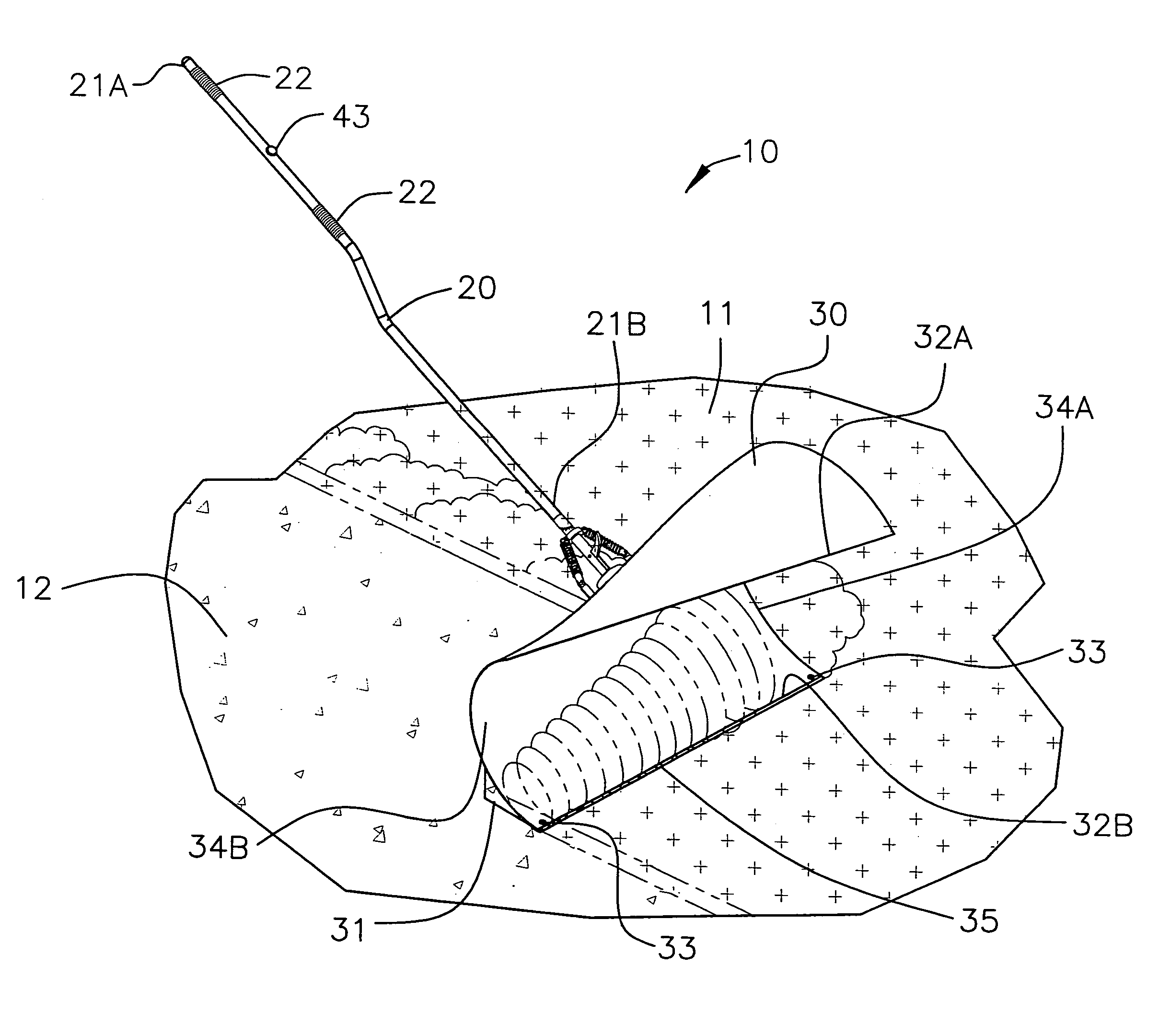
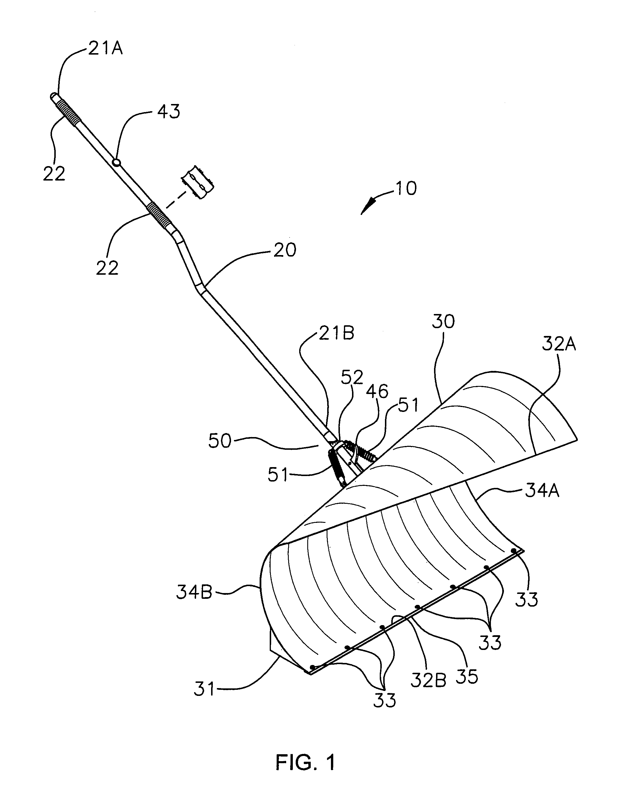
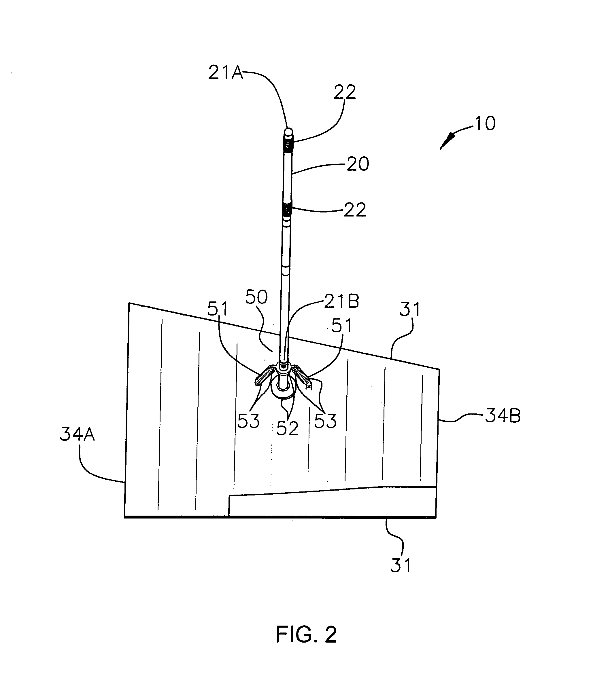
[0027]The apparatus of this invention is referred to generally in FIGS. 1-6 by the reference numeral 10 and is intended to provide a snow-shoveling apparatus. It should be understood that the apparatus 10 may be used to shovel many different types of debris and should not be limited in use to only shoveling snow.

[0028]Referring initially to FIGS. 1 and 6, the apparatus 10 includes an elongated shaft 20 that has axially offset proximal 21A and...


PUM


Abstract

An apparatus includes a shaft that has proximal and distal end portions. The shaft includes spaced grip covers conjoined about an outer surface thereof and is provided with a centrally registered sleeve formed therein. An arcuately shaped plow section is affixed to the distal end portion and includes a heel support that has an arcuately shaped top surface for assisting to maintain the plow section registered along a horizontal plane. The plow section further includes fastening members spaced along the bottom edge for removing the bottom edge to be sharpened or replaced. The apparatus further includes a mechanism for pivoting the plow section between alternate radial paths during operating conditions. A mechanism is included for automatically biasing the plow section to an equilibrium position after the plow section is biased to a pivoted position.

Description

CROSS REFERENCE TO RELATED APPLICATIONS[0001]Not Applicable.STATEMENT REGARDING FEDERALLY SPONSORED RESEARCH OR DEVELOPMENT[0002]Not Applicable.REFERENCE TO A MICROFICHE APPENDIX[0003]Not Applicable.BACKGROUND OF THE INVENTION[0004]1. Technical Field[0005]This invention relates to snow shovels and, more particularly, to a snow-shoveling apparatus for more effectively shoveling snow and the like.[0006]2. Prior Art[0007]The use of snow shovels is known in the prior art. More specifically, snow shovels heretofore devised and utilized are known to consist basically of familiar, expected, and obvious structural configurations, notwithstanding the myriad of designs encompassed by the crowded prior art which have been developed for the fulfillment of countless objectives and requirements.[0008]Conventional snow shovels are used to move articles such as snow and the like. In general, such snow shovels have an elongated handle and a slightly curved shovel portion attached to one end of the h...

Claims


Application Information

Patent Timeline
Patent Type & Authority Patents(United States)
IPC IPC(8): E01H5/02
CPCE01H5/02
Inventor PURVIS, RICHARD A.
Owner PURVIS RICHARD A
Why Eureka
Try Eureka