
Self-locking pin

a self-locking pin and pin technology, applied in the direction of threaded fasteners, screws, fastening means, etc., can solve the problems of affecting the installation process, affecting the installation effect, and requiring a large number of carefully machined parts, so as to facilitate the installation of the pin

Inactive Publication Date: 2005-03-29
PIVOT POINT
View PDF16 Cites 152 Cited by
  • Summary
  • Abstract
  • Description
  • Claims
  • Application Information

AI Technical Summary

Benefits of technology

The present invention, a self-locking pin, provides a pin with a uniquely shaped detent or plunger, which facilitates easy installation of the pin through an aperture in an object. In addition, the novel plunger in combination with a staking process non-rotatably retains the detent in its hole.

Problems solved by technology

A number of carefully machined parts, which are difficult to install properly, are required.
Additionally, the passageway extending along the axis of the bolt weakens the bolt.
Additionally the passage in the shaft weakens the bolt.

Method used


Image

  • Self-locking pin
  • Self-locking pin
  • Self-locking pin

Examples


Embodiment Construction

Although the disclosure hereof is detailed and exact to enable those skilled in the art to practice the invention, the physical embodiments herein disclosed merely exemplify the invention, which may be embodied in other specific structure. While the preferred embodiment has been described, the details may be changed without departing from the invention, which is defined by the claims.

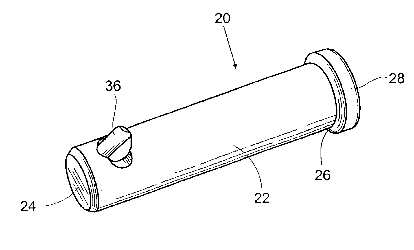
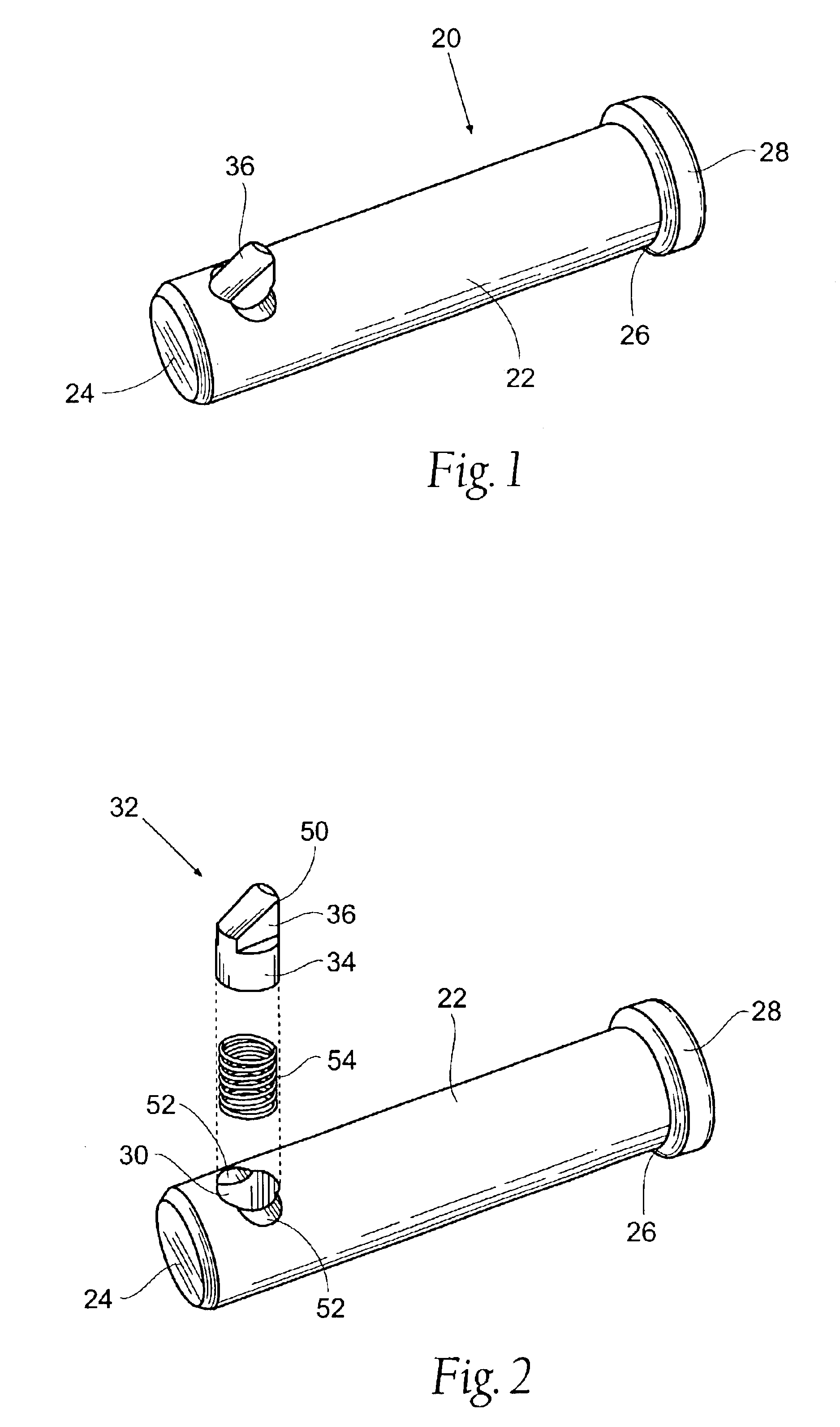
FIG. 1 illustrates the presently preferred embodiment of the self-locking pin 20 according to the invention. The pin 20 has a generally cylindrical shaft 22 with a first end 24 and a second end 26. The second end 26 may have an enlarged head 28.

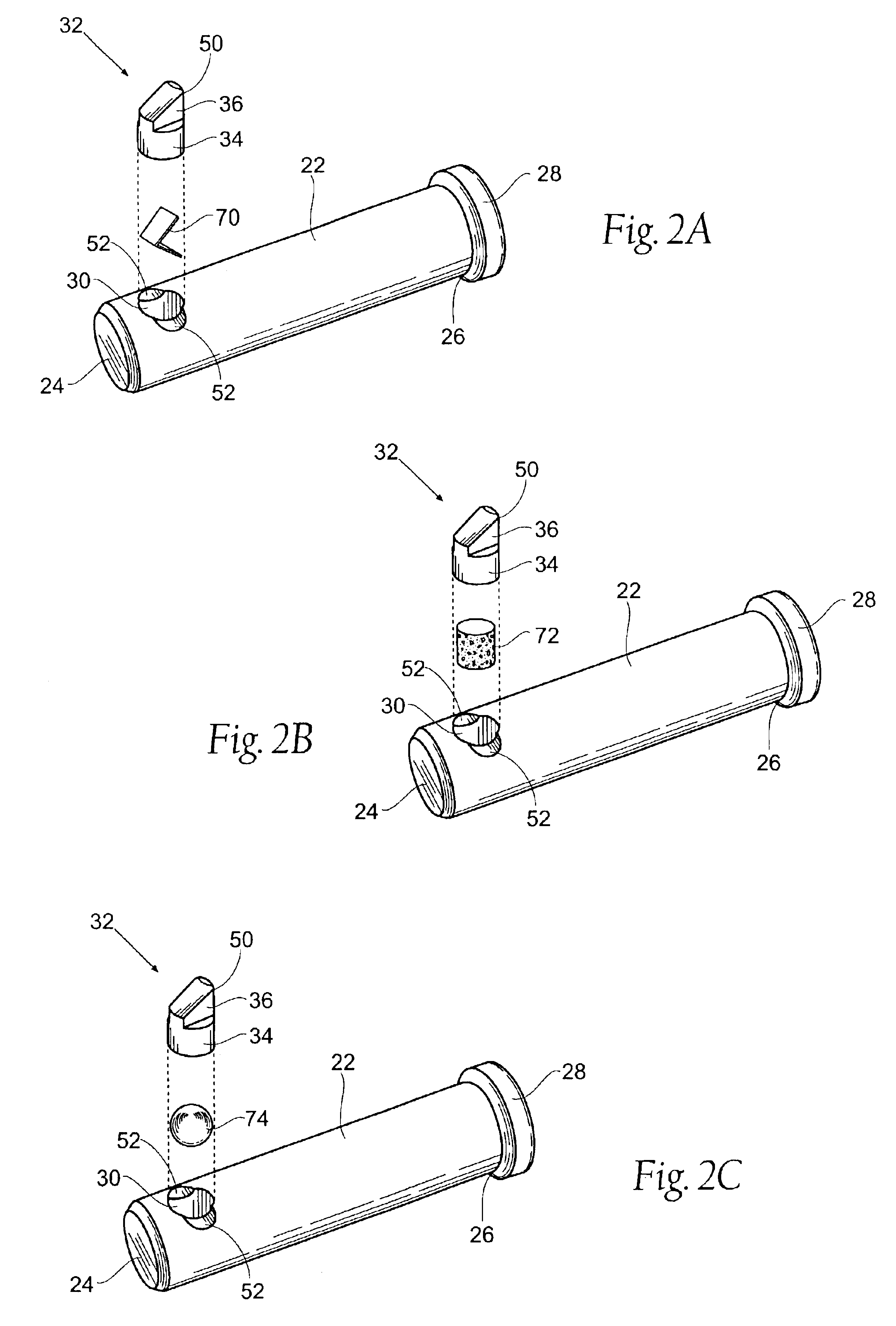
As seen in FIG. 2, a re-entrant bore 30 extends partway though the shaft 22 near the first end 24. The bore 30 extends radially inwardly towards the axis of the shaft. The bore 30 may or may not intersect the central longitudinal axis of the shaft. A plunger 32 is slidably disposed in the bore 30. The plunger 32 has a cylindrical portion 34 and a wedge-shaped por...


PUM


Abstract

A self-locking pin having a shaft, a headed end, and detent means biased in a bore in the pin. The portion of the detent or plunger that extends outwardly from the bore is wedge-shaped, while the portion of the plunger disposed inside the bore is cylindrical. A transitional angle is formed at the point where the configuration of the plunger changes from cylindrical to wedge-shaped. The transitional angle defines shoulders on either side of the plunger. The shaft is staked at points along the perimeter of the bore so that the inwardly extending surface created by the staking abuts the shoulders and prevents the plunger from rotating or being removed from the bore. In an alternate embodiment, the plunger may be rotated to a locked depressed position.

Description

BACKGROUND OF THE INVENTION1. Field of InventionThe invention relates to fasteners, namely threadless fasteners and more particularly to a threadless fastener for retaining two or more structures through apertures formed in each structure.Detent pins are well known in industry. Many of these pins fall into the category of safety bolts. Safety bolts have a threaded end to which a nut can be attached to as well as a detent mechanism along the length of the bolt. The main fastening mechanism in safety bolts is threading the nut on the end of the bolt. These products are often used in the aircraft industry so an extra safety factor is present in case vibrations cause the nut to loosen or someone forgets to tighten the nut. The detent mechanism is this extra safety factor. However, these dual fasteners make safety bolts more difficult and thus more expensive to manufacture. Additionally there are some applications where such a bolt cannot be used because it is either impractical or impos...

Claims


Application Information

Patent Timeline
IPC IPC(8): F16B19/04F16B21/00F16B19/10F16B21/12
CPCF16B21/125F16B19/109
Inventor BAUS, ROMYSWENSON, III, HARRY
Owner PIVOT POINT
Learn More