
Method of manufacturing patterned media

a technology of patterned media and manufacturing methods, which is applied in the manufacture of record carriers, coatings, coating carrier supports, etc., can solve the problems of affecting the fringing effect of magnetic fields from the magnetic head, the obvious problem of magnetic recording media installed on the hard disk drive, and the restriction of the improvement of track density

Inactive Publication Date: 2007-09-27
KK TOSHIBA
View PDF7 Cites 40 Cited by
  • Summary
  • Abstract
  • Description
  • Claims
  • Application Information

AI Technical Summary

Benefits of technology

[0018] Various embodiments according to the invention will be described hereinafter with reference to the accompanying drawings. In general, according to one embodiment of the present invention, there is provided a method of manufacturing a patterned media comprising a substrate and a magnetic recording layer on the substrate including protruded magnetic patterns and a nonmagnetic material filling recesses between the magnetic patterns, the method comprising: depositing a first nonmagnetic material to fill the recesses between the magnetic patterns; carrying out surface reforming of the first nonmagnetic material; depositing a second nonmagnetic material on the first nonmagnetic material; and etching back the second and first nonmagnetic materials.

Problems solved by technology

In recent years, magnetic recording media installed in hard disk drives (HDD) are obviously confronted with a problem that improvement in track density is restricted because of interference between adjacent tracks.
In particular, to reduce a fringing effect of magnetic fields from a magnetic head has become an important technical problem.
On the other hand, because a designed flying height of the flying head is about 10 nm, if deep grooves are present, flying characteristics of the head are made unstable.
Further, because dust is produced in the bias sputtering process and adheres to the media surface, a head crash is easily brought about.

Method used


Image

  • Method of manufacturing patterned media
  • Method of manufacturing patterned media
  • Method of manufacturing patterned media

Examples


example 1

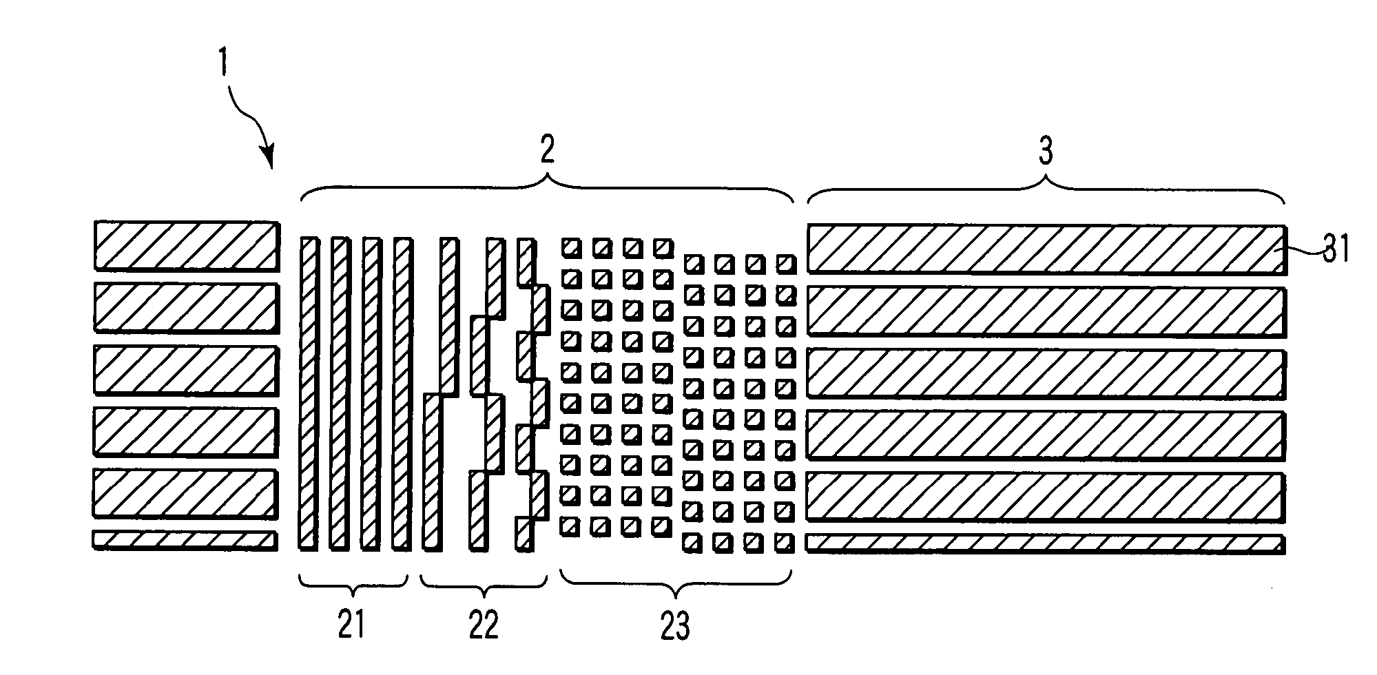
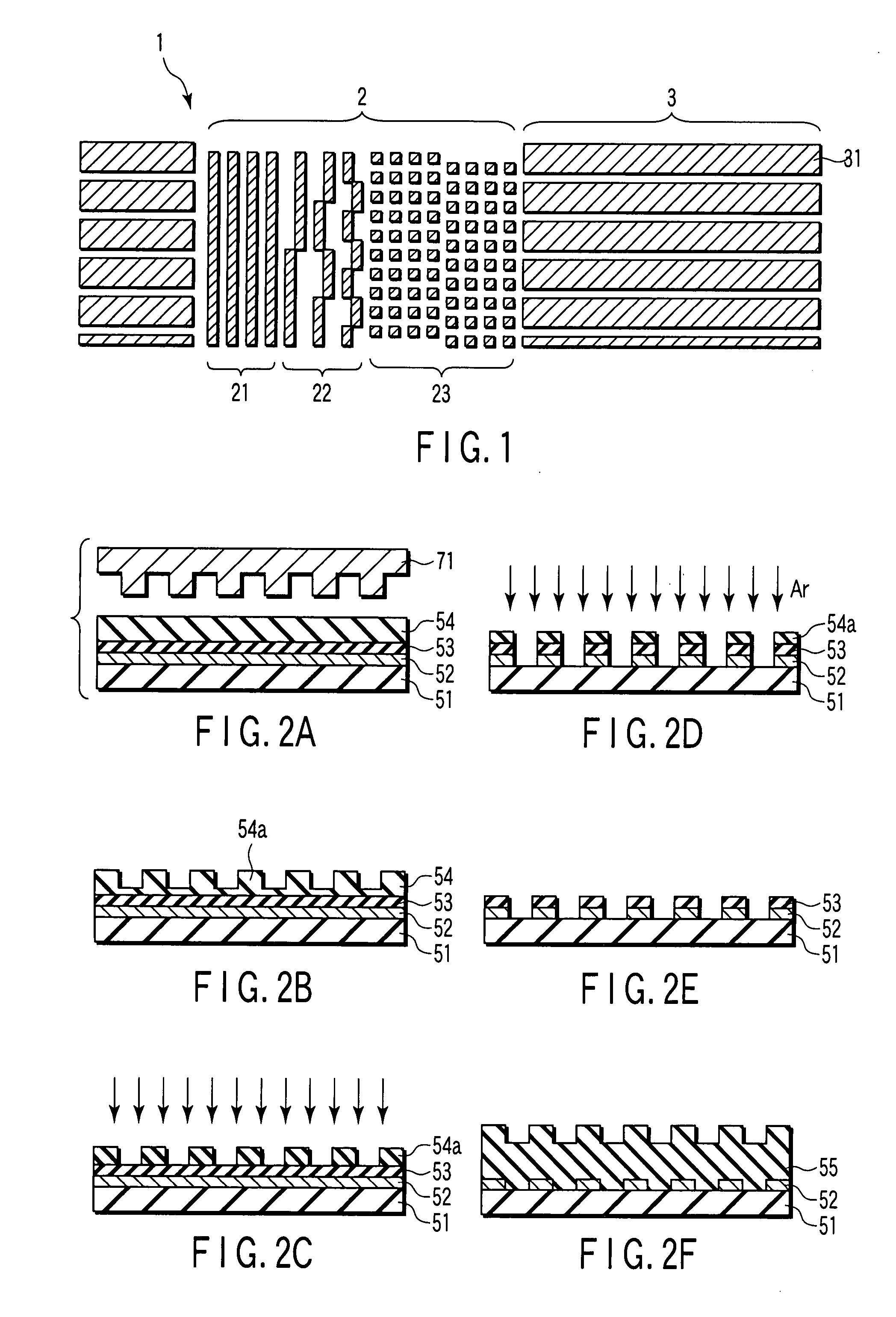
[0075] A DTR media was manufactured by the method shown in FIGS. 2A to 2J using a stamper having patterns of protrusions and recesses corresponding to servo patterns (preamble, address, and burst) and recording tracks as shown in FIG. 1.

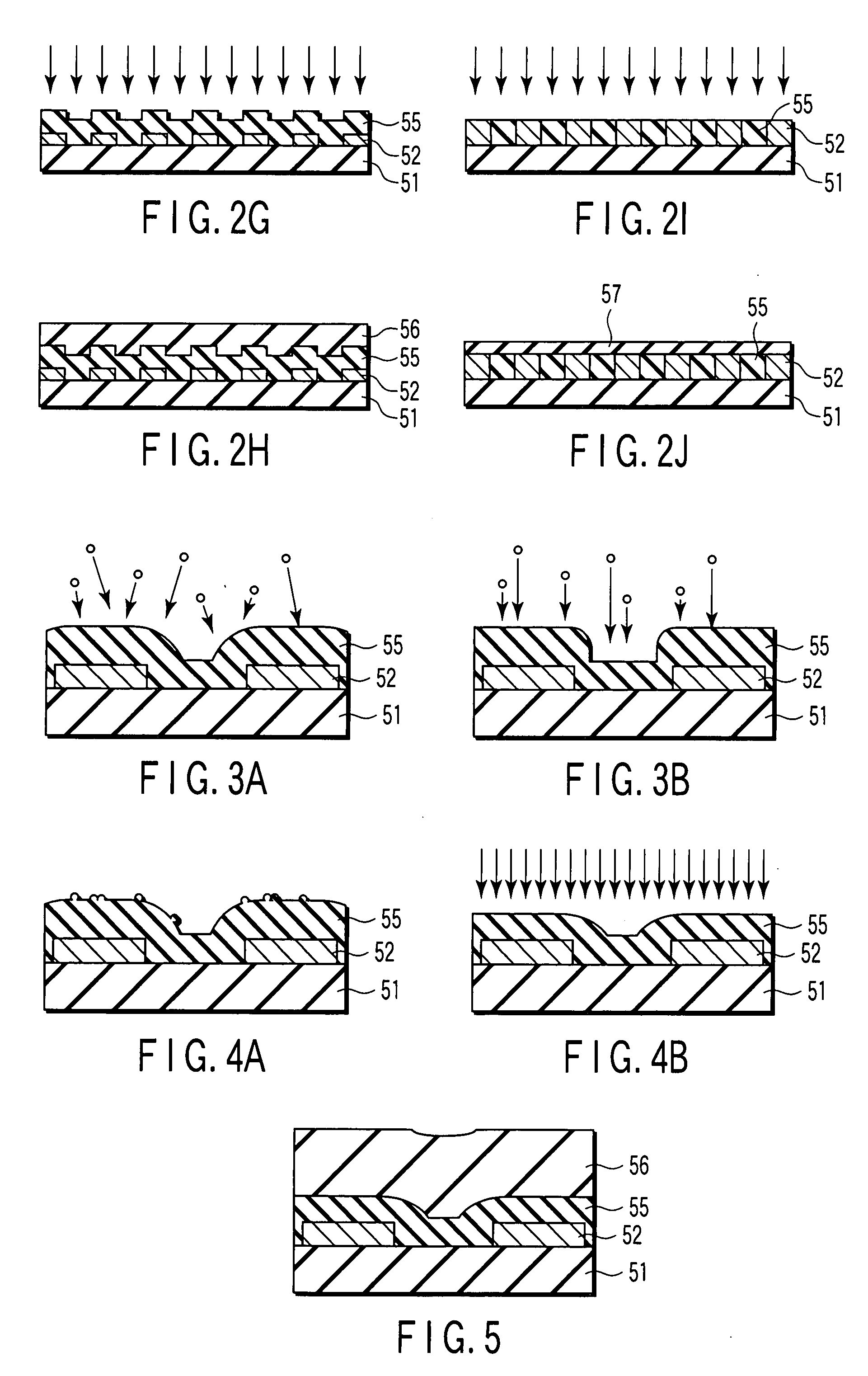
[0076] In the deposition process for the first nonmagnetic material 55 (FIG. 2F), 50 nm-thick carbon was deposited under an Ar pressure of as high as 7.0 Pa. In the surface reforming process (FIG. 2G), the first nonmagnetic material 55 was irradiated with Ar ions for one minute using an ECR ion gun under a microwave power of 800 W, and an accelerating voltage of 500V. In the deposition process for the second nonmagnetic material 56 (FIG. 2H), 10 nm-thick carbon was deposited under an Ar pressure of as low as 0.52 Pa. Other processes as described in FIGS. 2I and 2J were performed to manufacture the DTR media.

[0077] With respect to the resultant DTR media, a glide test was carried out by using a glide head of a designed flying height of 15 nm to whic...

example 2

[0080] A DTR media was manufactured by the same processes as those in Example 1 except that the surface reforming process (FIG. 2G) and the deposition process for the second nonmagnetic material (FIG. 2H) were repeated twice. More specifically, the following processes were performed. In the deposition process for the first nonmagnetic material 55 (FIG. 2F), 50 nm-thick carbon was deposited under an Ar pressure of as high as 7.0 Pa. In the surface reforming process (FIG. 2G), the first nonmagnetic material 55 was irradiated with Ar ions for one minute using an ECR ion gun under a microwave power of 800 W, and an accelerating voltage of 500V. In the deposition process for the second nonmagnetic material 56 (FIG. 2H), 10 nm-thick carbon was deposited under an Ar pressure of as low as 0.52 Pa. In the second surface reforming process (FIG. 2G), the second nonmagnetic material 56 was irradiated with Ar ions for one minute using an ECR ion gun under a microwave power of 800 W, and an accel...

example 3

[0082] A DTR media was manufactured as follows using the same stamper as in Example 1 and using SiO2 as a first nonmagnetic material.

[0083] In the deposition process for the first nonmagnetic material 55 (FIG. 2F), 50 nm-thick SiO2 was deposited under an Ar pressure of as high as 7.0 Pa. In the surface reforming process (FIG. 2G), the first nonmagnetic material 55 was irradiated with Ar ions for one minute using an ECR ion gun under a microwave power of 800 W, and an accelerating voltage of 500V. In the deposition process for the second nonmagnetic material 56 (FIG. 2H), 10 nm-thick carbon was deposited under an Ar pressure of as low as 0.52 Pa. Other processes as described in FIGS. 2I and 2J were performed to manufacture the DTR media.

[0084] With respect to the resultant DTR media, a glide test was carried out by using a glide head of a designed flying height of 15 nm to which an acoustic emission (AE) sensor is attached so as to examine contact of the head with the media. As a r...


PUM


Abstract

According to one embodiment, there is provided a method of manufacturing a patterned media having a substrate and a magnetic recording layer on the substrate including protruded magnetic patterns and a nonmagnetic material filling recesses between the magnetic patterns. The method includes depositing a first nonmagnetic material to fill the recesses between the magnetic patterns, carrying out surface reforming of the first nonmagnetic material, depositing a second nonmagnetic material on the first nonmagnetic material, and etching back the second and first nonmagnetic materials.

Description

CROSS-REFERENCE TO RELATED APPLICATIONS [0001] This application is based upon and claims the benefit of priority from Japanese Patent Application No. 2006-084095, filed Mar. 24, 2006, the entire contents of which are incorporated herein by reference. BACKGROUND [0002] 1. Field [0003] One embodiment of the present invention relates to a method of manufacturing a patterned media, more specifically to a method of manufacturing a patterned media having favorable surface flatness. [0004] 2. Description of the Related Art [0005] In recent years, magnetic recording media installed in hard disk drives (HDD) are obviously confronted with a problem that improvement in track density is restricted because of interference between adjacent tracks. In particular, to reduce a fringing effect of magnetic fields from a magnetic head has become an important technical problem. [0006] With respect to such a problem, a discrete track recording type patterned media (DTR media), in which recording tracks a...

Claims


Application Information

Patent Timeline
Patent Type & Authority Applications(United States)
IPC IPC(8): B05D5/12
CPCG11B5/855
Inventor KAMATA, YOSHIYUKISAKURAI, MASATOSHIKIKITSU, AKIRASHIROTORI, SATOSHI
Owner KK TOSHIBA
Learn More