Robot cleaner system having robot cleaner and docking station

Inactive Publication Date: 2007-10-04
SAMSUNG ELECTRONICS CO LTD
View PDF7 Cites 264 Cited by
  • Summary
  • Abstract
  • Description
  • Claims
  • Application Information

AI Technical Summary

Benefits of technology

[0011]Accordingly, it is an aspect of the present invention to provide a robot cleaner system having an improved docking structure between a robot cleaner and a docking station, which is capable of preven

Problems solved by technology

Therefore, the robot cleaner has a difficulty during a docking operation thereof due to the complicated structure for guiding the robot cleaner to an accurate docking position.
Further, since the conventional docking station performs a dust suction operation in a state where the suction inlet thereof simply faces the suction inlet of the robot cleaner, the conventional robot cleaner system has a problem in that it is difficult to stably keep the robot cleaner in a

Method used


Image

  • Robot cleaner system having robot cleaner and docking station
  • Robot cleaner system having robot cleaner and docking station
  • Robot cleaner system having robot cleaner and docking station

Examples


first embodiment

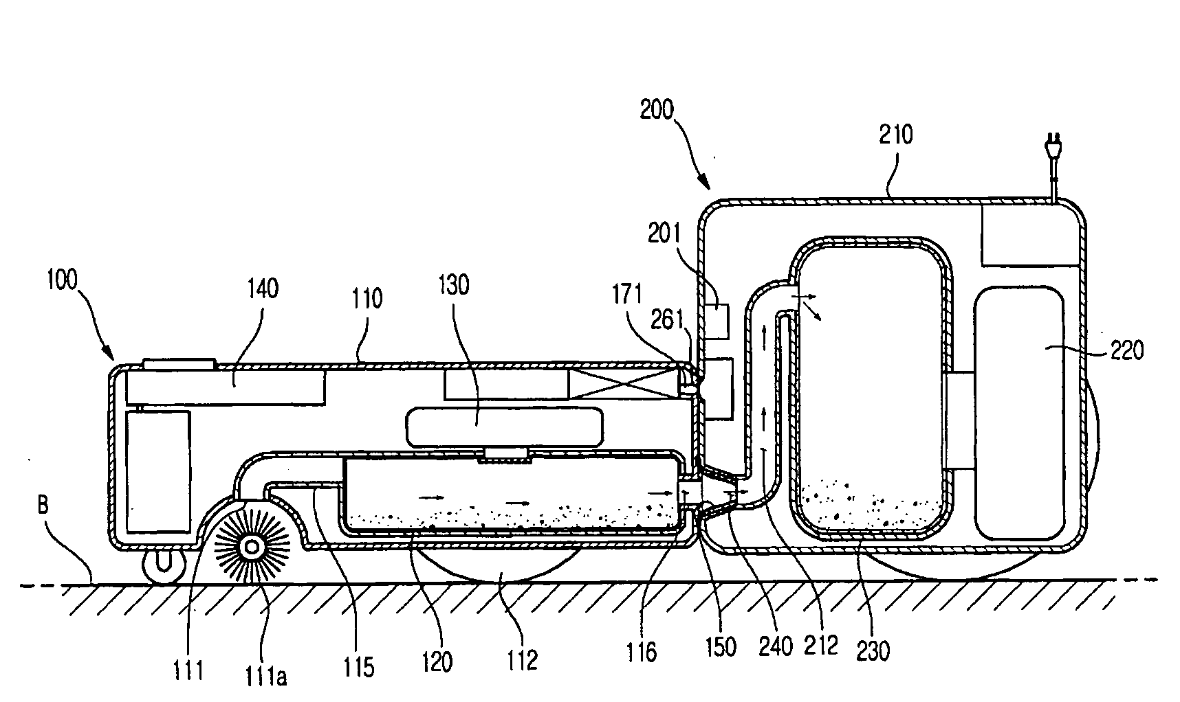
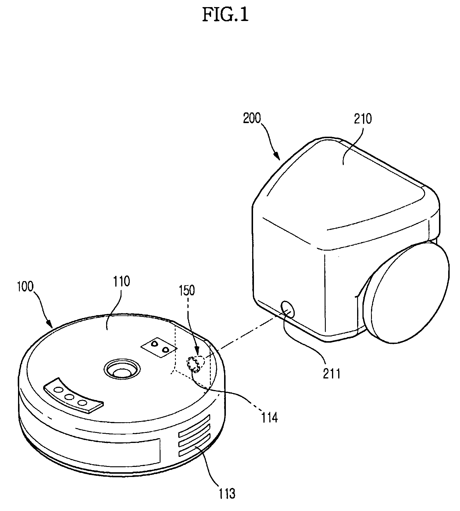
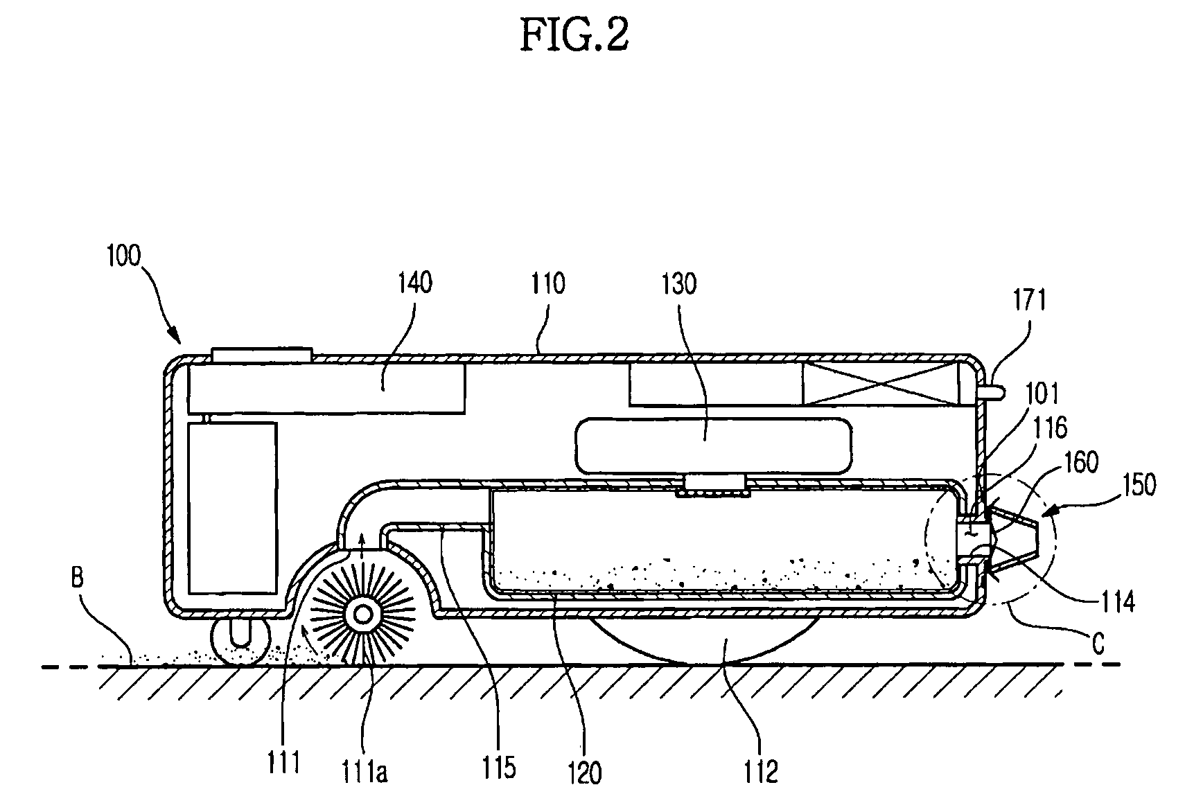
[0075]FIG. 1 is a perspective view illustrating the outer appearance of a robot cleaner system according to the present invention. FIGS. 2 and 3 are side sectional views, respectively, illustrating the configuration of a robot cleaner and a docking station of FIG. 1. FIG. 4 is a side sectional view of the robot cleaner system, illustrating a docked state between the robot cleaner and the docking station.

[0076]As shown in FIGS. 1-4, the robot cleaner system according to the first embodiment of the present invention comprises a robot cleaner 100 and a docking station 200. The robot cleaner 100 includes a robot body 110 formed with a dust inlet hole 111, and a first dust collector 120 mounted in the robot body 110 to store sucked dust and debris. The docking station 200 removes the dust and debris stored in the first dust collector 120 when being docked with the robot cleaner 100. In operation, the robot cleaner 100 performs an automatic cleaning operation while moving throughout an ar...

third embodiment

[0110]FIG. 10 is a sectional view illustrating a protrusion and a guide path provided in a robot cleaner system according to the present invention. FIG. 11 is a sectional view illustrating a docked state of a robot cleaner of FIG. 10. In the following description of the present embodiment, the same constituent elements as those of FIG. 5 are designated as the same reference numerals. The present embodiment has a difference in the installation structure of the protrusion as compared to the embodiment of FIG. 5. Hereinafter, only characteristic subjects of the present embodiment will be explained. As shown in FIGS. 10 and 11, a protrusion 180 of the robot cleaner 100 according to the present embodiment may be separated from the robot body 10, to move independently of the robot body 110. The protrusion 180 has one end 181 connected to the robot body 110 by use of an elastic joint member 190. The elastic joint member 190 consists of repeatedly formed pleats like a bellows. The use of th...

fourth embodiment

[0112]FIG. 12 is a sectional view illustrating a first opening / closing device and a guide path provided in a robot cleaner system consistent with the present invention. FIG. 13 is a sectional view illustrating a docked state of a robot cleaner of FIG. 12. In the present embodiment, the robot cleaner has no protrusion and opening / closing members of a first opening / closing device are configured to perform the role of the protrusion.

[0113]As shown in FIGS. 12 and 13, a first opening / closing device 160″ of the robot cleaner 100 according to an embodiment comprises opening / closing members 162″ installed to protrude out of the robot body 110, so as to perform the function of the above described protrusion 150a (See FIG. 5). The opening / closing members 162″ close the dust discharge hole 114 while the robot cleaner 100 performs the automatic cleaning operation, and are inserted into the dust suction hole 211 when the robot cleaner 100 is docked with the docking station 200. As soon as the d...


PUM


Abstract

A robot cleaner system having an improved docking structure between a robot cleaner and a docking station, which is capable of an easy docking operation of the robot cleaner and preventing loss of a suction force generated in the docking station. The robot cleaner includes a docking portion to be inserted into a dust suction hole of the docking station upon a docking operation. The docking portion may be a protrusion, which protrudes out of a robot body to be inserted into a dust suction path defined in the docking station, the protrusion communicates a dust discharge hole of the robot cleaner with the dust suction path of the docking station. The robot cleaner system includes a coupling device to keep the robot cleaner and the docking station in their docked state. The coupling device is configured to have a variety of shapes.

Description

CROSS-REFERENCE TO RELATED APPLICATIONS[0001]This application claims the benefit of Korean Patent Application No. 10-2006-0030718 filed on Apr. 4, 2006, No. 10-2006-0030923 filed on Apr. 5, 2006, No. 10-2006-0031413 filed on Apr. 6, 2006, No. 10-2006-0032347 filed on Apr. 10, 2006 and No. 10-2006-0034579 filed on Apr. 17, 2006 in the Korean Intellectual Property Office, the disclosures of which are incorporated herein by reference.BACKGROUND OF THE INVENTION[0002]1. Field of the Invention[0003]The present invention relates to a cleaner system. More particularly, to a robot cleaner system including a docking station, which is installed to suck and remove dust and debris stored in a robot cleaner.[0004]2. Description of the Related Art[0005]A cleaner system is a device used to remove dust in a room for cleaning the room. A conventional vacuum cleaner collects dust and loose debris by a suction force generated from a low-pressure unit included therein. A conventional robot cleaner remo...

Claims


Application Information

Patent Timeline
IPC IPC(8): A47L5/00
CPCA47L9/009A47L2201/024A47L9/106
Inventor HAHM, JUNG YOONEDUARD, KURGIWEE, HOONJEONG, JIN HAJOO, JAE MAN
Owner SAMSUNG ELECTRONICS CO LTD
Why Eureka
Try Eureka