
Illuminated artificial tree

a technology of artificial trees and lights, applied in non-electric lighting, lighting and heating apparatus, lighting support devices, etc., can solve the problems of one string of electrical lights failing, time-consuming replacement process, and extreme time-consuming to illuminate artificial trees in the manner described, so as to achieve a less time-consuming and easy-to-replace process

Inactive Publication Date: 2007-10-04
HICKS LARRY O +1
View PDF26 Cites 142 Cited by
  • Summary
  • Abstract
  • Description
  • Claims
  • Application Information

AI Technical Summary

Benefits of technology

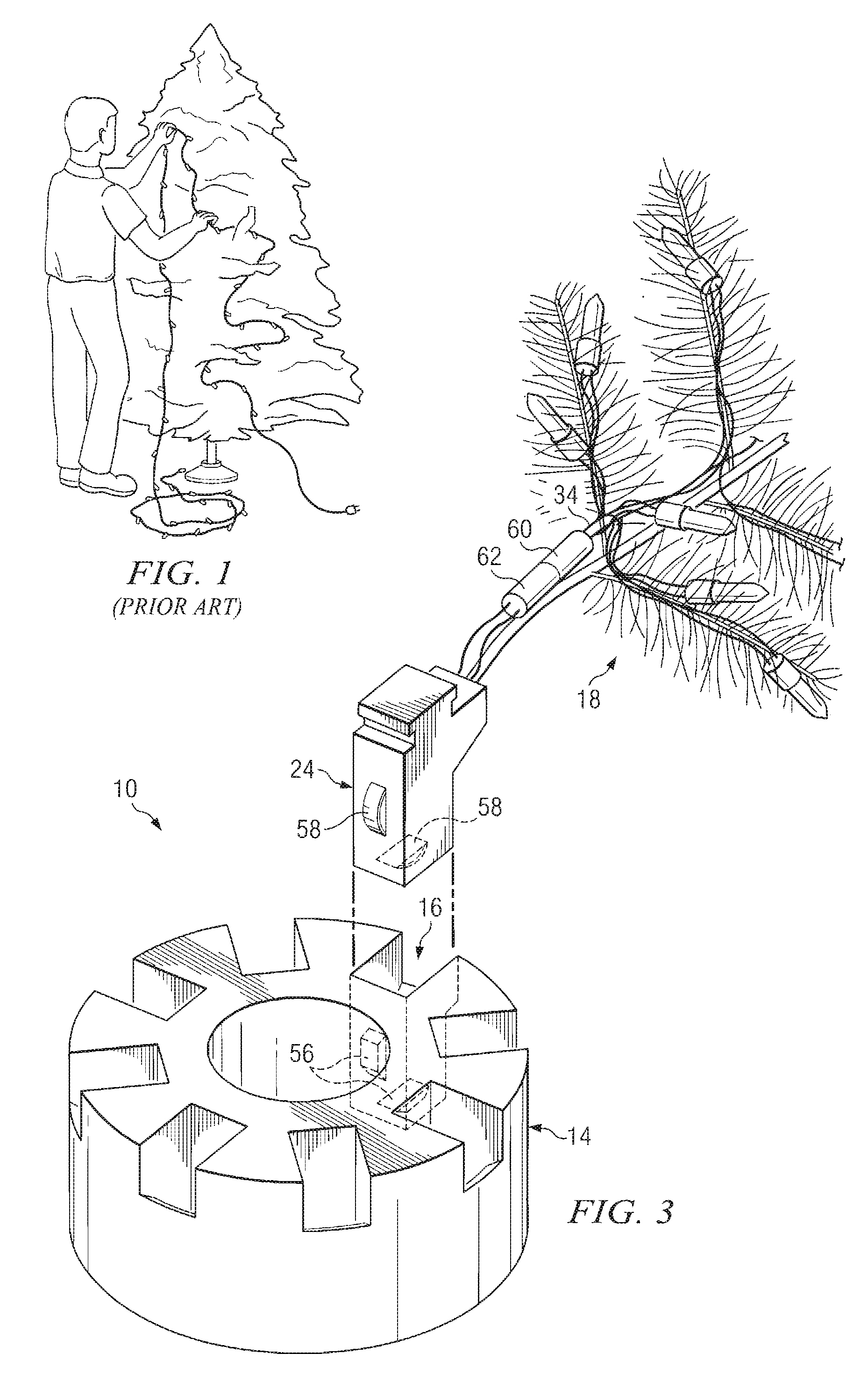
[0011]Each branch has a string of electrical lights attached therearound. Each string of lights comprises a first fusible link plug which plugs into a matching plug located on the boot. The matching plug on the boot supplies power to the string of lights once the boot is engaged in the cavity. The string of lights on each branch is independent from any string of lights on other branches; therefore, a failure of one string of lights on one branch does not affect any other string of lights on the tree. In addition to not causing any other lights on other branches to fail, each branch can be individually removed from the tree for replacement of the string of lights without removing any other branches or lights from the tree resulting in a much easier and less time-consuming process to replace lights than the time or effort required in the prior art.

Problems solved by technology

It is extremely time consuming to illuminate artificial trees in the manner described above.
In addition to the extended amount of time required to illuminate a tree as described above, it is common for one string of electrical lights to fail when multiple strings of lights are connected.
The replacement process is time consuming as well.
Further, because the strings of electrical lights are connected one to another it is common for the failure of one string to affect other strings as well.
There are also safety hazards associated with connecting multiple strings together.
Although most extension cords are only rated for a certain electrical load many consumers are unaware of such load restrictions and the hazards associated with failing to practice such restrictions.
Overloading electrical extension cords can result in fires resulting in property damage and ultimately loss of life if a fire occurs in a building where any occupants are unable to escape.
In addition to failed strings of lights such trees generally require a significant amount of space for storage when not in use and / or can be very cumbersome and difficult to assemble and dis-assemble.

Method used


Image

  • Illuminated artificial tree
  • Illuminated artificial tree
  • Illuminated artificial tree

Examples


Embodiment Construction

[0020]Referring to the drawings, and in particular to FIG. 1, there is shown a perspective view of an individual attempting to illuminate an artificial tree in the prior art. The difficulties encountered in the prior art include isolating branches, individually wrapping isolated branches with strings of electrical lights, isolating a string of electrical lights that has failed once failure becomes apparent, and the effect of failed strings of lights on other strings.

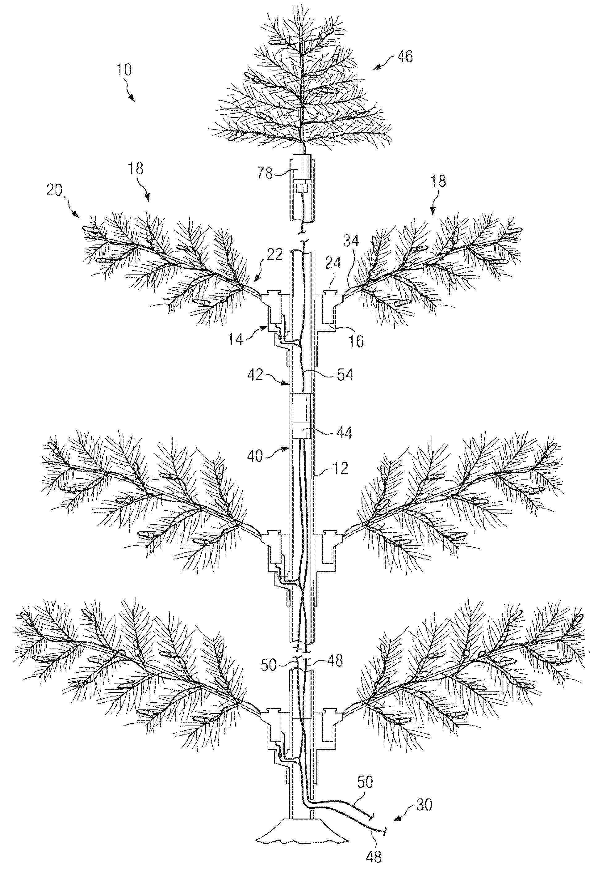
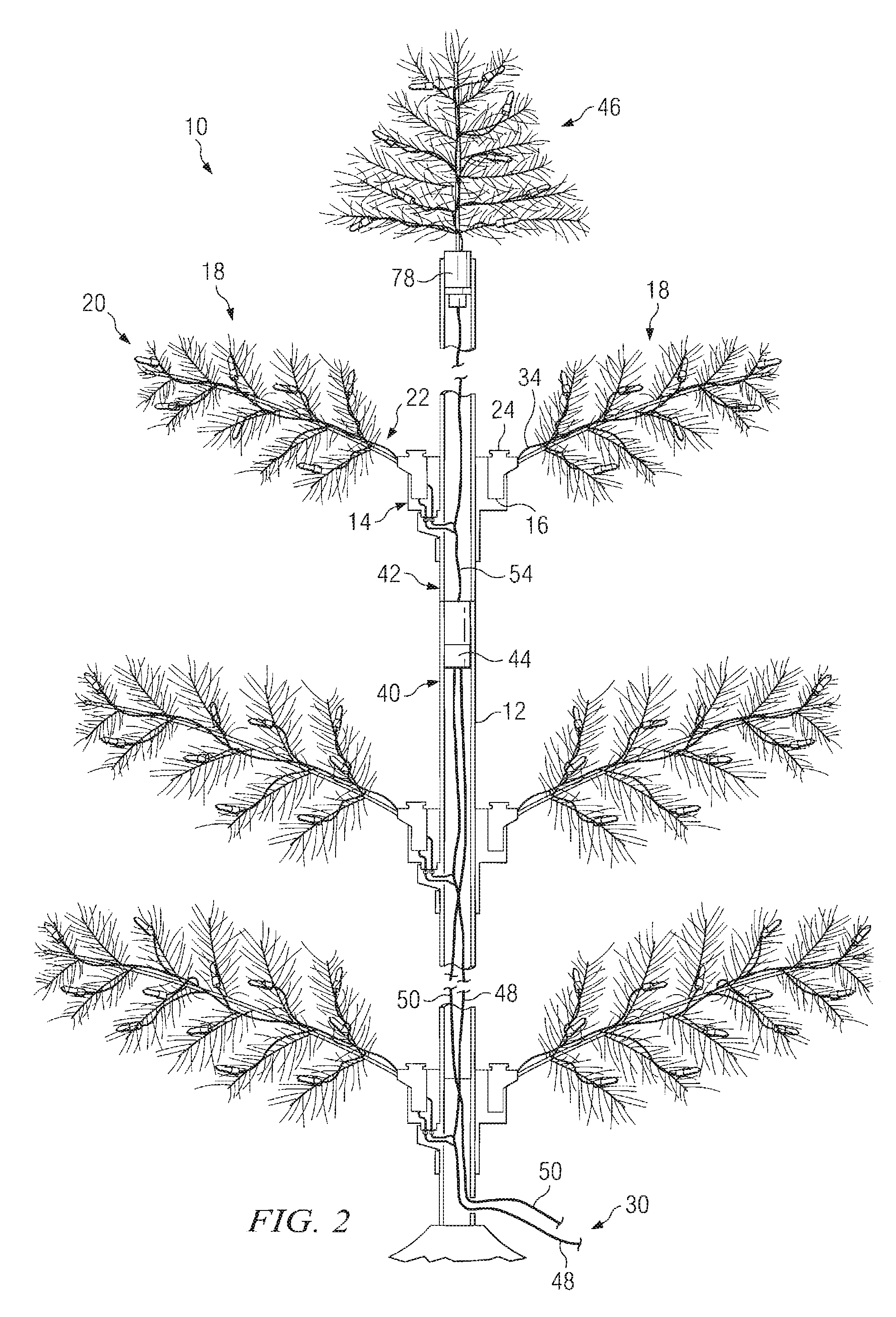
[0021]Referring now to FIG. 2 there is shown an artificial illuminated tree 10 comprising one embodiment of the invention. The tree 10 comprises a center pole 12 having a plurality of mounts 14 supported thereon, each mount 14 comprising multiple cavities 16 for receiving branches 18 therein. Each branch 18 comprises a distal end 20 and a proximal end 22, the proximal end 22 comprising a boot 24 for securing the branch 18 into one of the cavities 16 of the mount 14. Electrical power is provided to each individual cavity ...


PUM


Abstract

An illuminated artificial tree having a center pole with mounts thereon for receiving and supporting branches about the center pole and means for providing electricity to electrical lighting about each branch individually so that the electrical lighting about each individual branch can be replaced without affecting the electrical lighting about the other branches.

Description

CROSS-REFERENCE TO RELATED APPLICATION[0001]Applicant claims priority based on provisional patent application Ser. No. 60 / 744,150 filed Apr. 2, 2006, the entire content of which is incorporated herein by reference.TECHNICAL FIELD[0002]This invention relates to the fields of electrical lighting and artificial trees.BACKGROUND AND SUMMARY OF THE INVENTION[0003]It is common and well known to illuminate trees, particularly artificial trees. It is especially common for individuals to seek to illuminate artificial trees during the Christmas season.[0004]Artificial trees are often illuminated by wrapping strings of electrical lights about the branches thereof. Typically, numerous strings of electrical lights are required, each string being plugged into the next to form a long, single string of electrical lights that is plugged into an electrical wall outlet. If a large number of strings of lights is used it may be necessary to form multiple long strings that are each plugged continuously e...

Claims


Application Information

Patent Timeline
IPC IPC(8): F21S13/14
CPCA47G33/06F21W2121/04F21S13/14F21S4/001F21S4/10
Inventor HICKS, LARRY O.HICKS, DAVID ALLEN
Owner HICKS LARRY O
Learn More