
Electric power connector adapting structure

Inactive Publication Date: 2007-10-04
TOPOWER COMP IND CO LTD
View PDF7 Cites 1 Cited by
  • Summary
  • Abstract
  • Description
  • Claims
  • Application Information

AI Technical Summary

Benefits of technology

[0004] In view of the foregoing shortcomings of the prior art connector adapting structure, the present invention improves the power management of the adapting cable of an electric power connector by providing a novel electric connector adapting structure to overcome the shortcomings of the prior art structure.
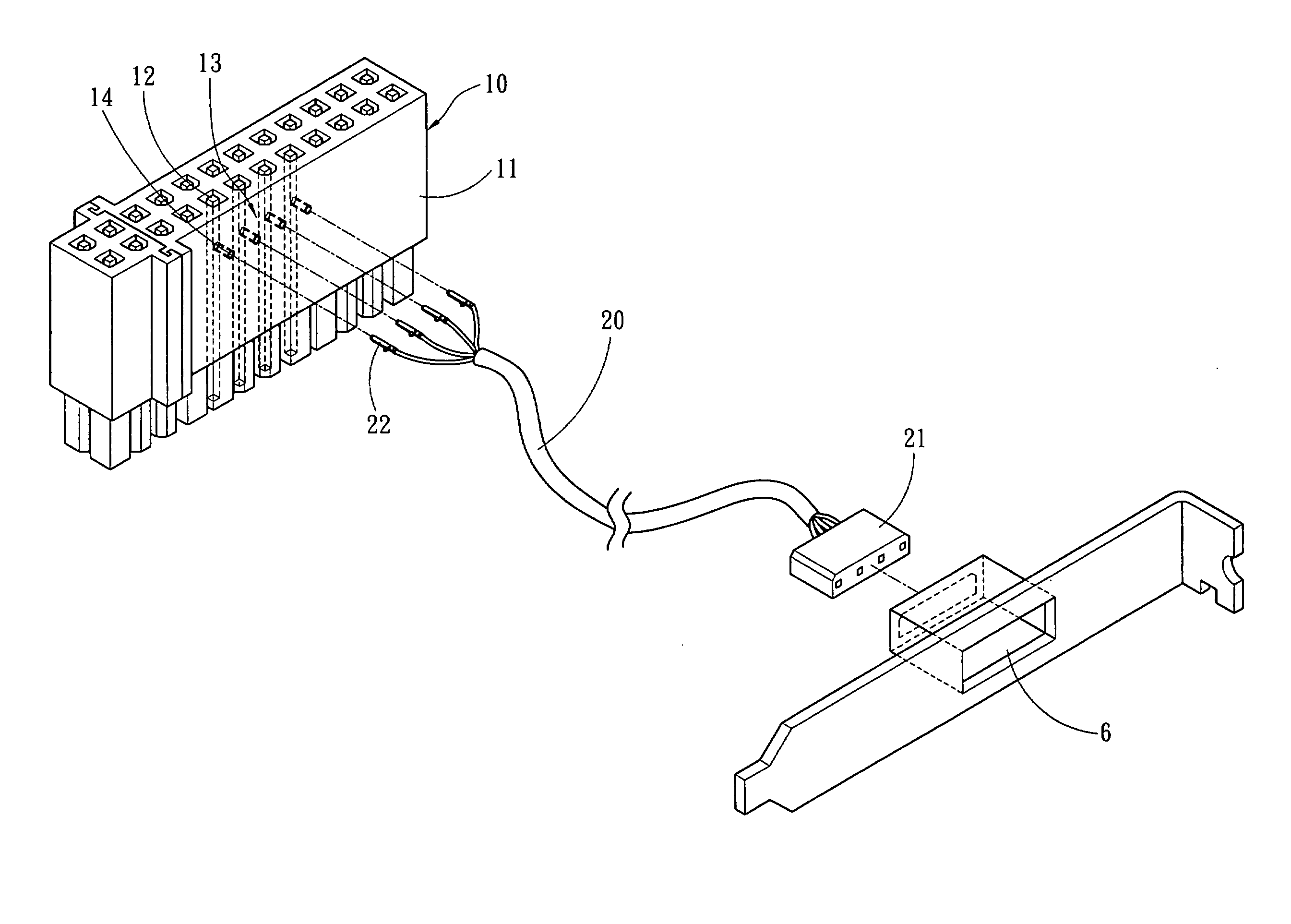
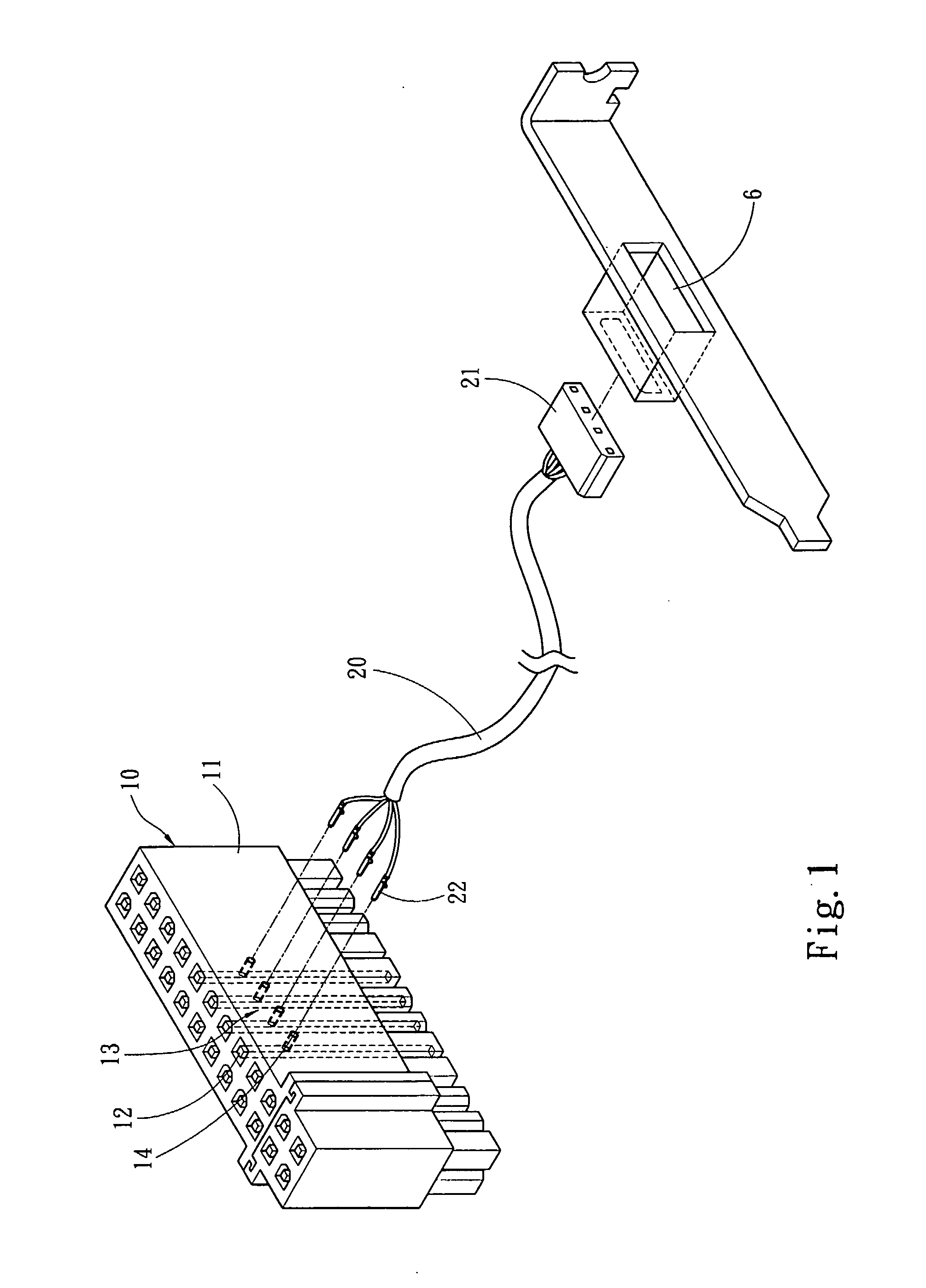
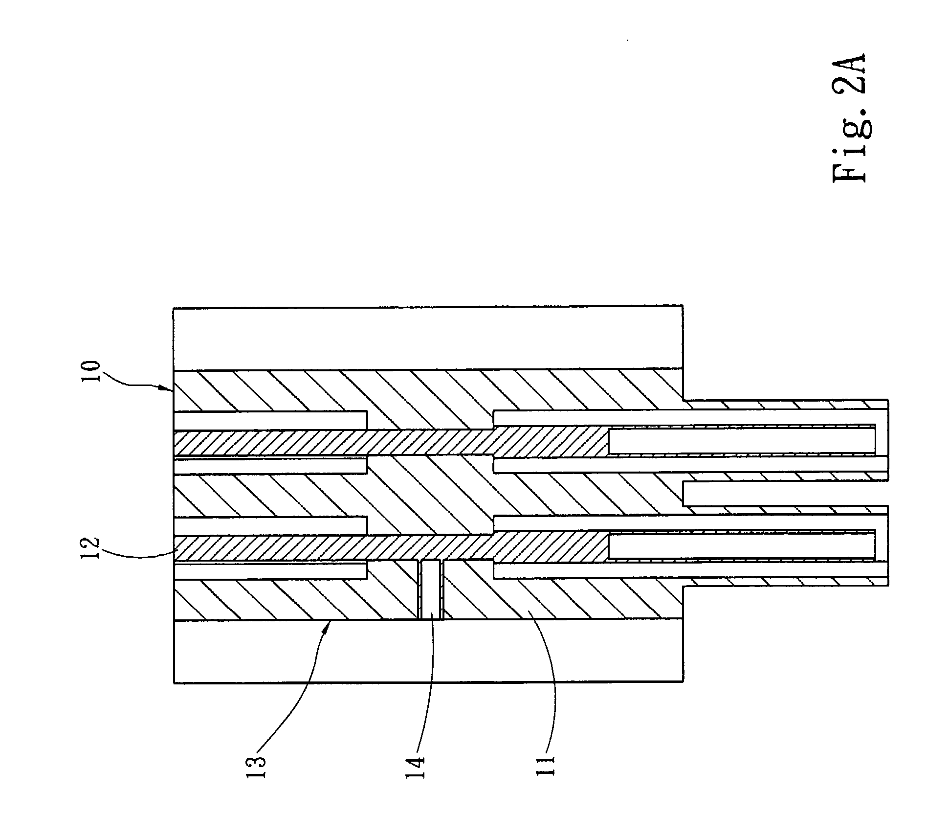
[0005] Therefore, it is a primary objective of the present invention to provide an electric power connector that connects an adapting cable at a lateral side of the connector, and the connector is also connected to a power output port of an electric power cable of a power supply for achieving the adapting effect, and the connector is further connected to an adapting cable for supplying electric power to a port. The connector includes an insulating body and a plurality of electric power terminals installed in the insulating body, and the invention includes an electric connecting portion disposed at the insulating body and corresponding to a vertical side of an open side of the electric power terminals for connecting the adapting cable, such that the adapting cable supplies electric power with an equivalent electric potential to the port, so as to avoid using excessive cable materials or having a poor cable management for the wiring space.

Problems solved by technology

However, the motherboard has already installed many other cables and wires, and such electric power connector adapting structure may interfere with the original wires and cables installed on the motherboard, and thus making the cable management of the motherboard more difficult.
Furthermore, the motherboard usually comes with many ports, but the prior art adapting cable installed on the same side of the power cable of the electric power connector may make their installation very difficult, if not impossible.

Method used


Image

  • Electric power connector adapting structure
  • Electric power connector adapting structure
  • Electric power connector adapting structure

Examples


Embodiment Construction

[0012] The present invention will now be described in more detail hereinafter with reference to the accompanying drawings as follows:

[0013] Referring to FIGS. 1 and 2A for the pictorial drawing and the cross-sectional view of the present invention respectively, the present invention relates to an electric power connector adapting structure, the connector 10 is connected to an electric power cable 3 of a power supply 2 for the electric power transmission of a motherboard 5 (as shown in FIG. 5) and the connector 10 is a 20-pin or 24-pin connector 10, and the connector 10 is connected to an adapting cable 20 for supplying electric power to a port 21, and the connector 10 includes an insulating body 11 and a plurality of electric power terminals 12 installed in the insulating body 11, and the insulating body 11 includes an electric connecting portion 13 electrically coupled to the electric power terminal 12 and corresponding to a vertical side of an open side of the electric power term...


PUM


Abstract

An electric power connector adapting structure includes a connector connected to an electric power cable of a power supply and adapted to an adapting cable for supplying electric power to a port, and the connector installs an electric power terminal therein. The invention includes an electric connecting portion corresponding to a vertical side of an open side of the electric power terminal for connecting an adapting cable, so that the port is electrically coupled to the electric power terminal with an equivalent electric potential, and the connector is connected to a power output port of a power supply for the use of an adapter. The present invention connects an adapting cable to a lateral side of the connector to achieve an easy installation and effectively avoid using excessive cable materials or having a poor cable management.

Description

FIELD OF THE INVENTION [0001] The present invention relates to an electric power connector, and more particularly to an electric power connector adapting structure that has an adapting cable connected to a lateral side of the electric power connector. BACKGROUND OF THE INVENTION [0002] Since computers are very popular, they have become an indispensable electric appliance or tool for household users or companies, and all components such as a central processing unit, a motherboard, a hard disk drive and an optical drive of a computer require electric power supplied by a power supply. Referring to R.O.C. Pat. Publication No. M253980 entitled “Power output connector of a power supply” for a traditional power supply, the traditional electric power connector of the traditional power supply comes with a 20-pin port or a 24-pin port on a motherboard to meet the requirements of electronic peripherals and devices with different specifications, and the pin number of hard disk drives and floppy...

Claims


Application Information

Patent Timeline
IPC IPC(8): H01R27/00
CPCY10S439/912H01R12/7041
Inventor CHEN, MICHAEL
Owner TOPOWER COMP IND CO LTD
Learn More