
Power management based on combined user interface and sensor inputs

Inactive Publication Date: 2012-09-13
RICOH KK
View PDF6 Cites 18 Cited by
  • Summary
  • Abstract
  • Description
  • Claims
  • Application Information

AI Technical Summary

Benefits of technology

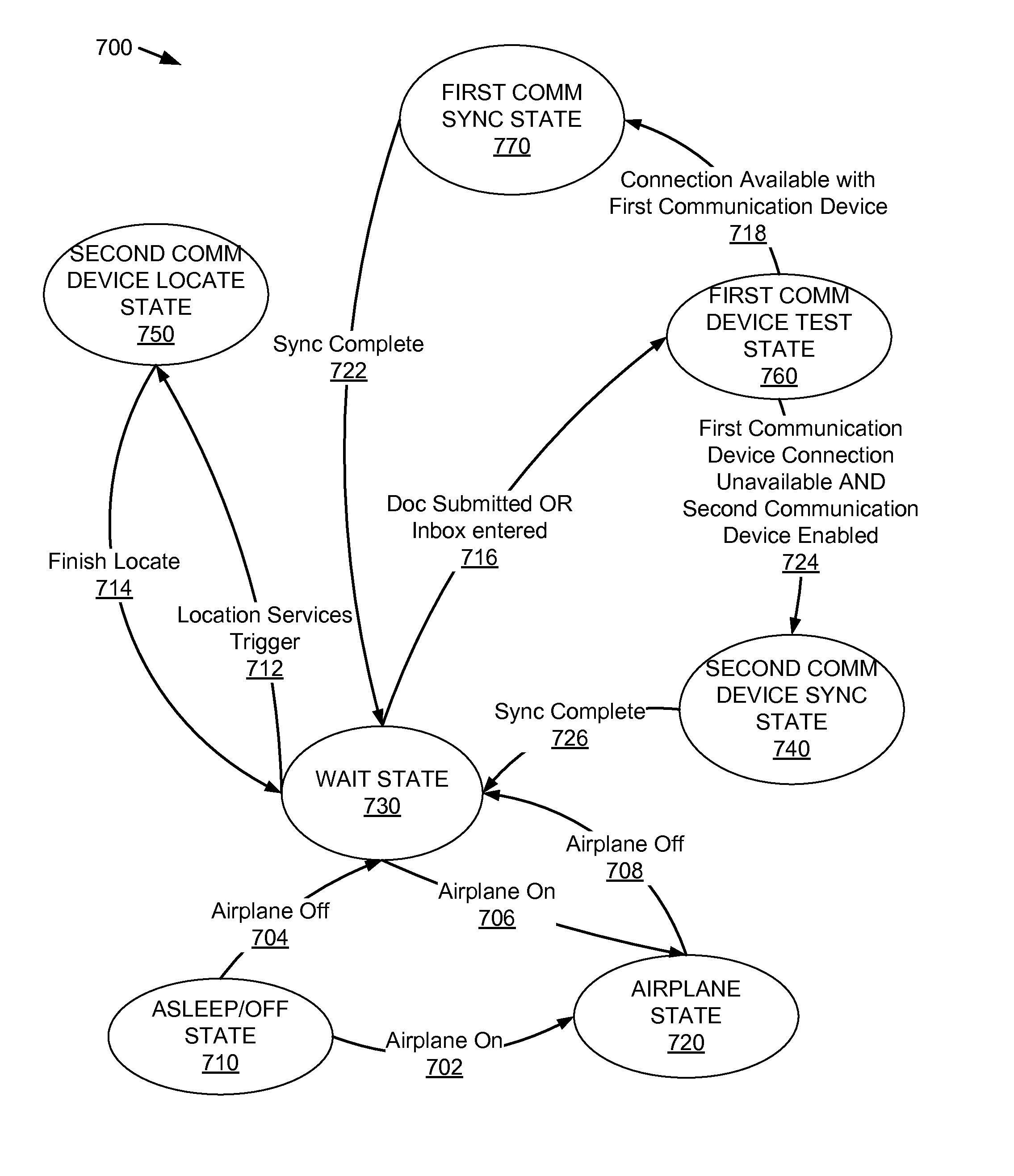
[0011]In one embodiment, the communication unit included in the device includes a first communication device and a second communication device, allowing the device to communicate with different networks using the different communication devices. To further improve power management, the device may transition between communication device operating states modifying power consumption by the first communication device and the second communication device. In one embodiment, the device operates in an asleep / off communication state where power is not supplied from the power supply to the display device, the processor, the first communication device and to the second communication device. Responsive to receiving an input, the device determines whether to operate in an airplane mode, and responsive to determining to operate in an airplane mode, power is supplied to the display device and the processor while power is not supplied to the first communication device and to the second communication device. However, responsive to determining not to operate in the airplane mode, the device operates in a wait state where power is supplied to the display device and the processor. In the wait state, a low amount of power is supplied to the first communication device power is not supplied to the second communication device.

Problems solved by technology

For example, many current portable computing devices include a transceiver for transmitting and receiving data using a network compliant with the International Mobile Telecommunications-2000 (IMT-2000) standard, commonly called a “3G network” and a second transceiver for transmitting and receiving data using a Wireless Fidelity network, commonly called a “WiFi network.” However, operating multiple transmitters increases the power consumed by a portable computing device, often draining the portable computing device's battery more rapidly.
To improve battery life, many portable computing devices allow different wireless transceivers to be disabled, which limits the network connectivity of the portable computing device while increasing its battery life.
However, conventional techniques for enabling and disabling transceivers require users to manually enable and disable transceivers, increasing complexity and requiring active user involvement as the location or operation of the portable computing device changes.
Display devices and other components also further increase the power consumption of portable computing devices.
However, these actions require a specific user interaction to modify display device or other component operation.
Like manually enabling or disabling transceivers, manual modification of a display device, or of another component, increases user complexity and requires a user to remember what has been done to a display device or other component and to frequently modify display device or other component operation as use of the portable computing device changes.

Method used


Image

  • Power management based on combined user interface and sensor inputs
  • Power management based on combined user interface and sensor inputs
  • Power management based on combined user interface and sensor inputs

Examples


first embodiment

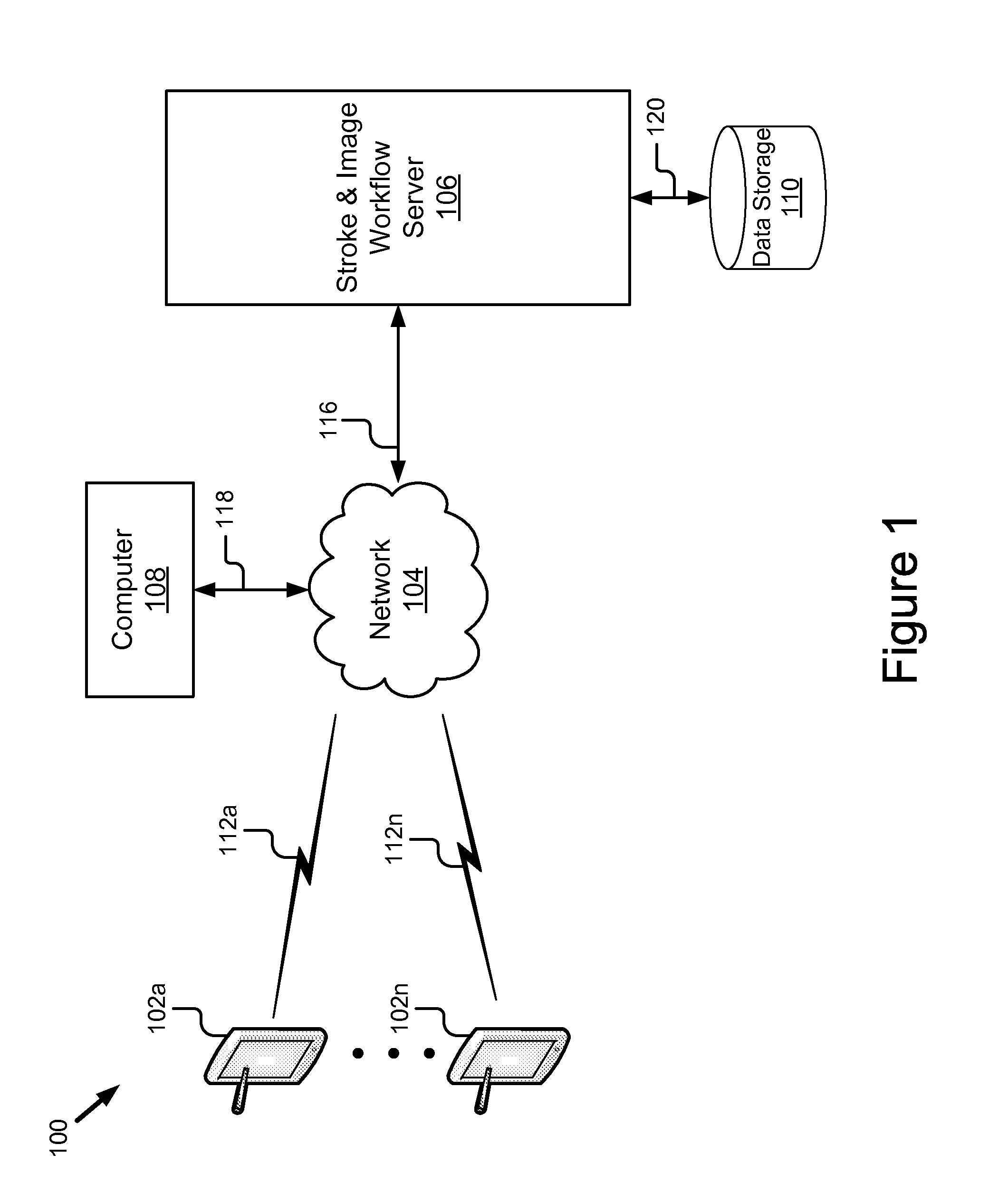
[0060]In a first embodiment, the document transfer module 316 is client software operational on the computing pad 202 that maintains a directory structure that serves as an inbox. The document transfer module 316 moves documents from a corresponding inbox on the stroke and image workflow server 106 to this directory. Once a document in the inbox of the computing pad 202 has been annotated and the user inputs the submit instruction, the document transfer module 316 removes the document from the directory structure and transfers it to the stroke and image workflow server 106 for further processing.

second embodiment

[0061]In a second embodiment, the document transfer module 316 is an e-mail client that is capable of receiving and sending e-mails having attachments. The e-mail client is operable on the processor 302. Mail servers commonly use either the POP or IMAP protocols to talk to mail clients, and the computing pad 202 is configured to use either. The messages are in a format the computing pad 202 can directly use, e.g. an attachment of image files. The messages are in a format that requires conversion on the computing pad 202, e.g. a pdf document. Alternatively, a special mail server could provide conversion of messages so that the pad does not need to support multiple formats. In the case of multiple devices being used in a workflow to distribute work that must only be done once e.g. as in the departmental in-box described above, using IMAP is advantageous. Multiple devices 102a-n may be configured as clients with the same IMAP server and ‘username.’ The group of devices 102a-n might dis...

third embodiment

[0062]In a third embodiment, the document transfer module 316 is a routine for performing file transfer. Various file transfer methods can be used to move documents on and off the computing pad 202. The computing pad 202 could run an ftp, http, or webdav server and other devices could push or pull documents on the computing pad 202. The computing pad 202 could also be configured to get or post new documents to an external server, again via ftp, http, rsync, webdav, or another protocol.


PUM


Abstract

Power usage of a portable computing device is modified to more efficiently use a power supply included in the portable computing device. Power usage by different components of the portable computing device is modified based on use of the portable computing device to allow dynamic modification of power consumption. The portable computing device includes data describing various power management states and the portable computing device transitions between different power management states as it is used, modifying the power consumption of various components in different power management states. Various communication device operating states are also defined to modify power usage by communication devices included in the portable computing device based on device usage.

Description

BACKGROUND OF THE INVENTION[0001]1. Field of the Invention[0002]The present embodiment of invention relates to portable computing devices and, in particular, to managing power consumption of a portable computing device based on workflow of the portable computing device.[0003]2. Description of the Background Art[0004]The use of portable computing devices has become commonplace for many users. In addition to having a conventional desktop computer, many users also have some type of portable computing device. Examples of present-day computing devices include electronic devices for reading. Smaller portable computing devices include a plethora of smart phones. There have also been increased sales of notebook laptops and tablet computers offering different levels of processing capability and size.[0005]Portable computing devices commonly send and receive data using wireless communication. Accordingly, most portable computing devices include one or more wireless transceivers to transmit an...

Claims


Application Information

Patent Timeline
IPC IPC(8): G06F1/32
CPCG06F1/3265Y02B60/1282Y02B60/1242G06F1/3287Y02D10/00
Inventor PIERSOL, KURT W.AMEMIYA, KANAERHODES, BRADLEY J.SCHWARTZ, EDWARD L.GUDAN, KENNETH F.
Owner RICOH KK
Learn More