Display drive device and liquid crystal display device

Inactive Publication Date: 2007-10-11
KK TOSHIBA
View PDF4 Cites 5 Cited by
  • Summary
  • Abstract
  • Description
  • Claims
  • Application Information

AI Technical Summary

Benefits of technology

[0007] One or more of the problems outlined above may be addressed by embodiments of the invention. Broadly speaking, systems and methods are provided to derive information identifying the power usage characteristics of software programs, and the information is used to determine the manner in which the software programs will be executed, thereby improving the management of power within the device executing the programs.

Problems solved by technology

Therefore, there is a problem that the power consumption and electromagnetic interference (EMI) of the source driver increase by operation of these circuits.
Especially, as the number of source drivers increases by increase of the number of signal lines accompanying high integration and high resolution in recent years, the power consumption and EMI of a source driver increases further.

Method used


Image

  • Display drive device and liquid crystal display device
  • Display drive device and liquid crystal display device
  • Display drive device and liquid crystal display device

Examples


Embodiment Construction

[0027] Various other objects, features and attendant advantages of the present invention will be more fully appreciated as the same becomes better understood from the following detailed description when considered in connection with the accompanying drawings in which like reference characters designate like or corresponding parts throughout the several views and more particularly to FIG. 1 thereof.

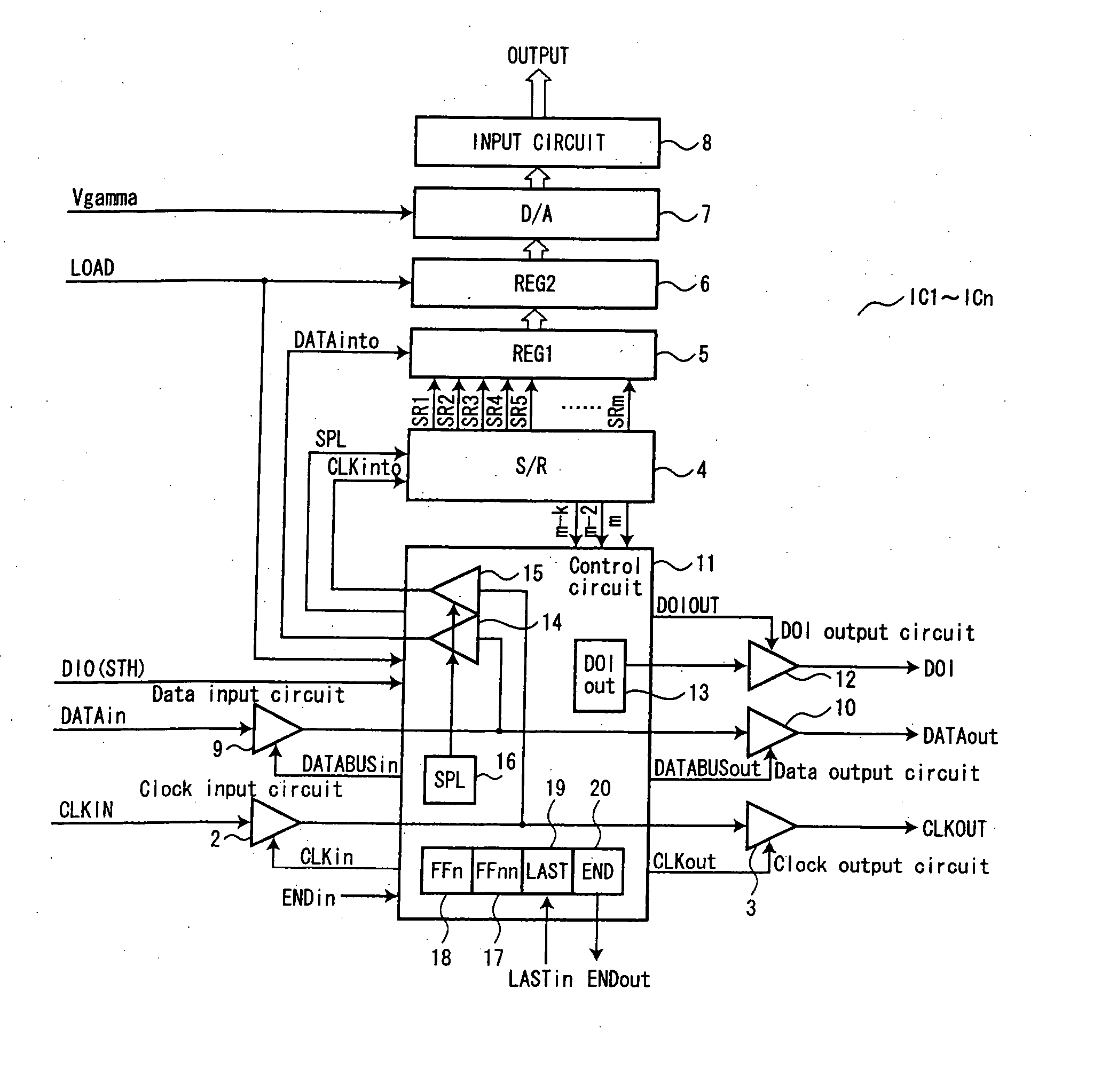
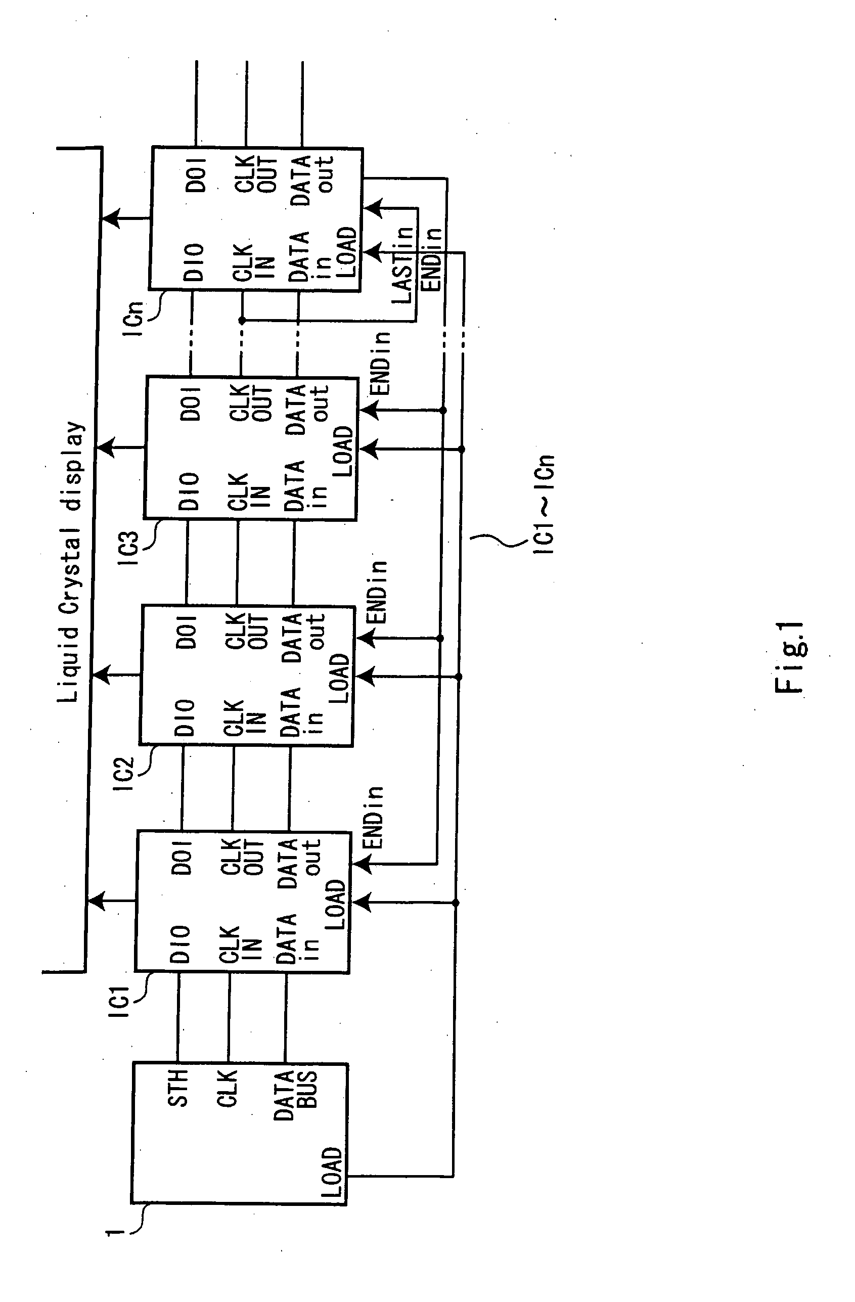
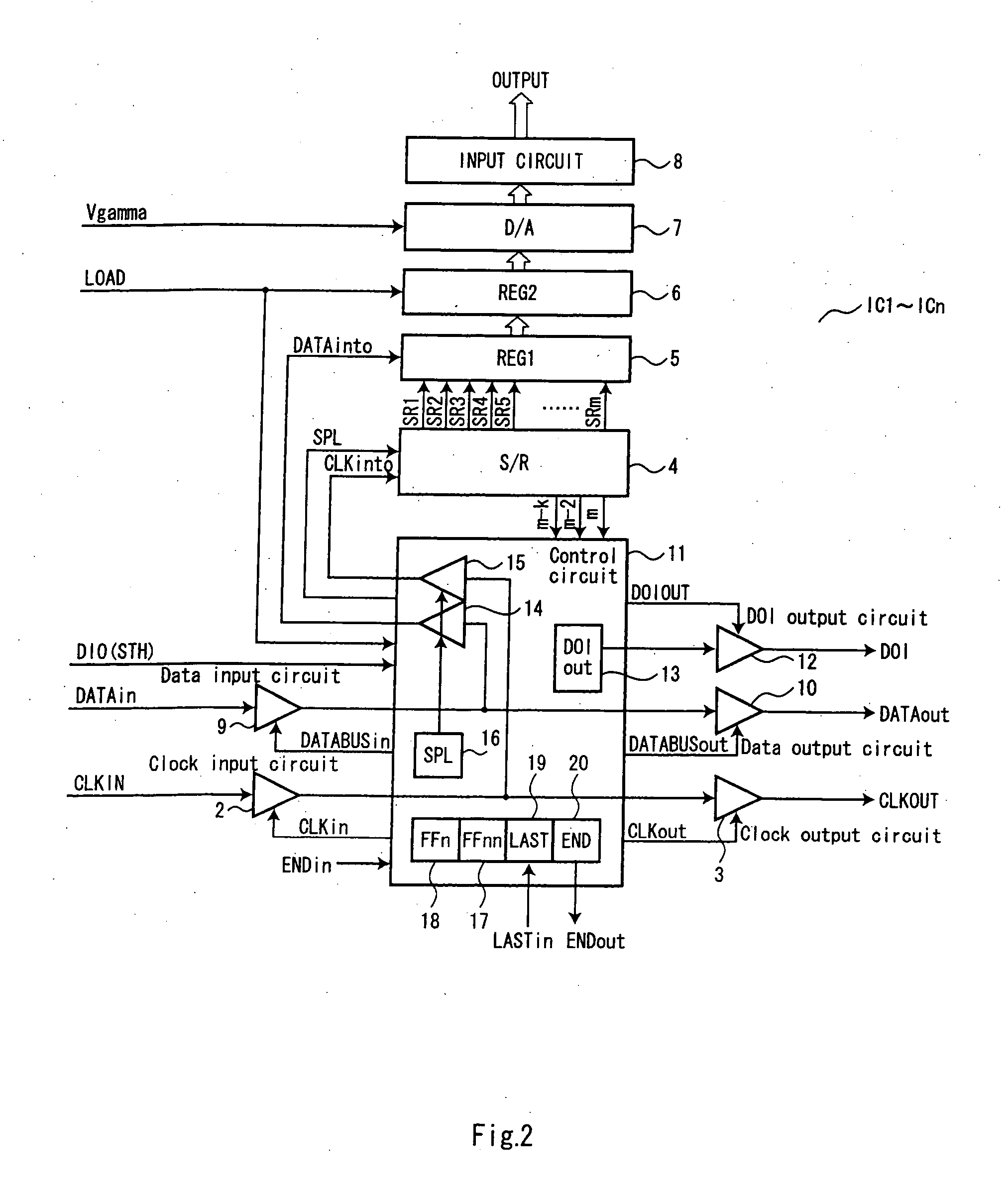
[0028] As shown in FIG. 1, the signal-line drive circuit includes two or more source drivers IC1-ICn by which cascade connection is carried out, and controller 1 which controls source drivers IC1-ICn. Below, cascade connection of source drivers IC1-ICn is described, and an example for which each source driver drives m signal lines is explained.

[0029] Controller 1 supplies start pulse signal STH to source driver IC 1. Controller 1 supplies digital pixel data to source driver IC 1 through a data bus, and supplies each digital pixel data DATA to source drivers IC2-ICn via each source driver...


PUM


Abstract

A display drive device includes a plurality of cascade connected source drivers, each having a pixel data input circuit for receiving and outputting a pixel data, a clock input circuit for receiving a clock signal for latching a pixel data outputted from the pixel data input circuit, a latch circuit for latching the pixel data outputted from the pixel data input circuit in synchronization with the clock signal, a data output circuit for outputting the pixel data inputted to the clock input circuit, a clock output circuit outputting the clock signal inputted to the clock input circuit, a generation circuit generating a data take-in signal for instructing the source driver to start to drive, and a detector for latching a start pulse signal providing a display timing or the data take-in signal outputted from the generation circuit in synchronization with the clock signal; and a controller for controlling start of drive of the clock output circuit or the pixel data output circuit of the first source driver by the time the data take-in signal is outputted from the generation circuit from a time when the first source driver starts to latch the pixel data.

Description

CROSS REFERENCE TO THE RELATED APPLICATION [0001] This application is based upon and claims the benefit of priority from the prior Japanese Application No. 2006-105742, filed Apr. 6, 2006, the entire contents of which are incorporated by reference herein. BACKGROUND OF THE INVENTION [0002] 1. Field of the Invention [0003] This invention relates to display drive device and liquid crystal display device. More particularly, the invention pertains to a display drive device and a liquid crystal display device having cascade connection. [0004] 2. Description of the Related Art [0005] A signal line of a liquid crystal display can be driven using a source driver. Since the number of the signal lines which can be driven by one source driver is limited, usually a cascade connection is made of two or more source drivers, which drive all signal lines. In order that source drivers are constituted by a cascade connection, the data lines go through the source driver. When obtaining bigger images o...

Claims


Application Information

Patent Timeline
IPC IPC(8): G09G3/36
CPCG09G3/3688G09G2330/06G09G2330/021G09G2310/08
Inventor ARAI, TOORU
Owner KK TOSHIBA
Why Eureka
Try Eureka