Base station, radio terminal and radio communication method

a radio terminal and radio communication technology, applied in the direction of wireless communication, transmission path division, signalling characterisation, etc., can solve the problems of reducing the transmission rate of uplink to the base station, the inability to assign subbands to the terminals, and the amount of information of feedback from the terminal to the base station

Inactive Publication Date: 2007-10-04
KK TOSHIBA
View PDF0 Cites 51 Cited by
  • Summary
  • Abstract
  • Description
  • Claims
  • Application Information

AI Technical Summary

Problems solved by technology

However, according to the method described in JP-A 2005-244958 (KOKAI), the terminal feeds back CQIs of only subbands in a good channel condition, and therefore if these subbands are assigned to some other terminals, there is a problem that the subbands cannot be assigned to the terminal.
On the other hand, there may also be a method of feeding back CQIs of all subbands, but adopting this method causes the amount of information of feedback from the terminal to the base station to become enormous, causing a problem that the transmission rate on the uplink to the base station decreases.

Method used


Image

  • Base station, radio terminal and radio communication method
  • Base station, radio terminal and radio communication method
  • Base station, radio terminal and radio communication method

Examples


first embodiment

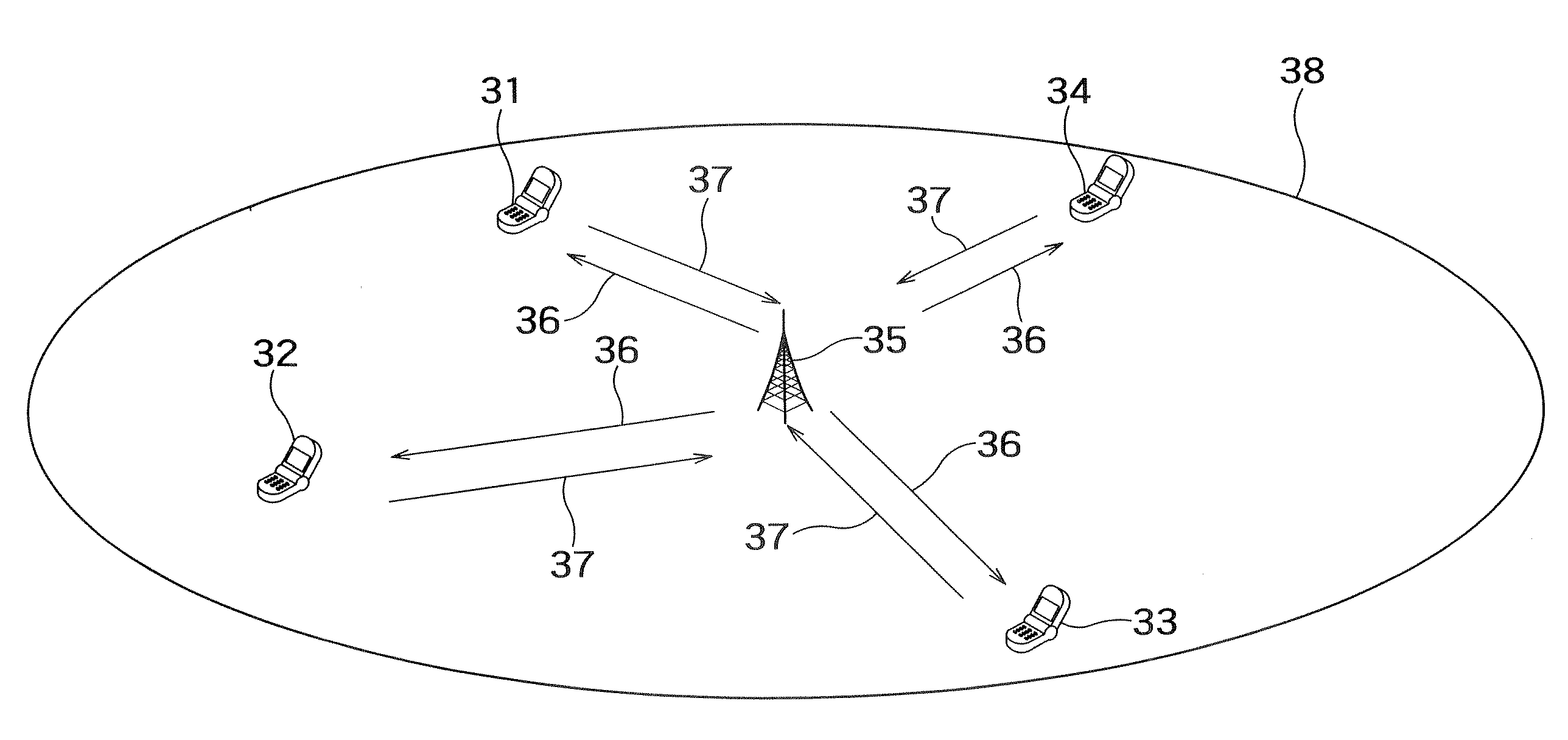
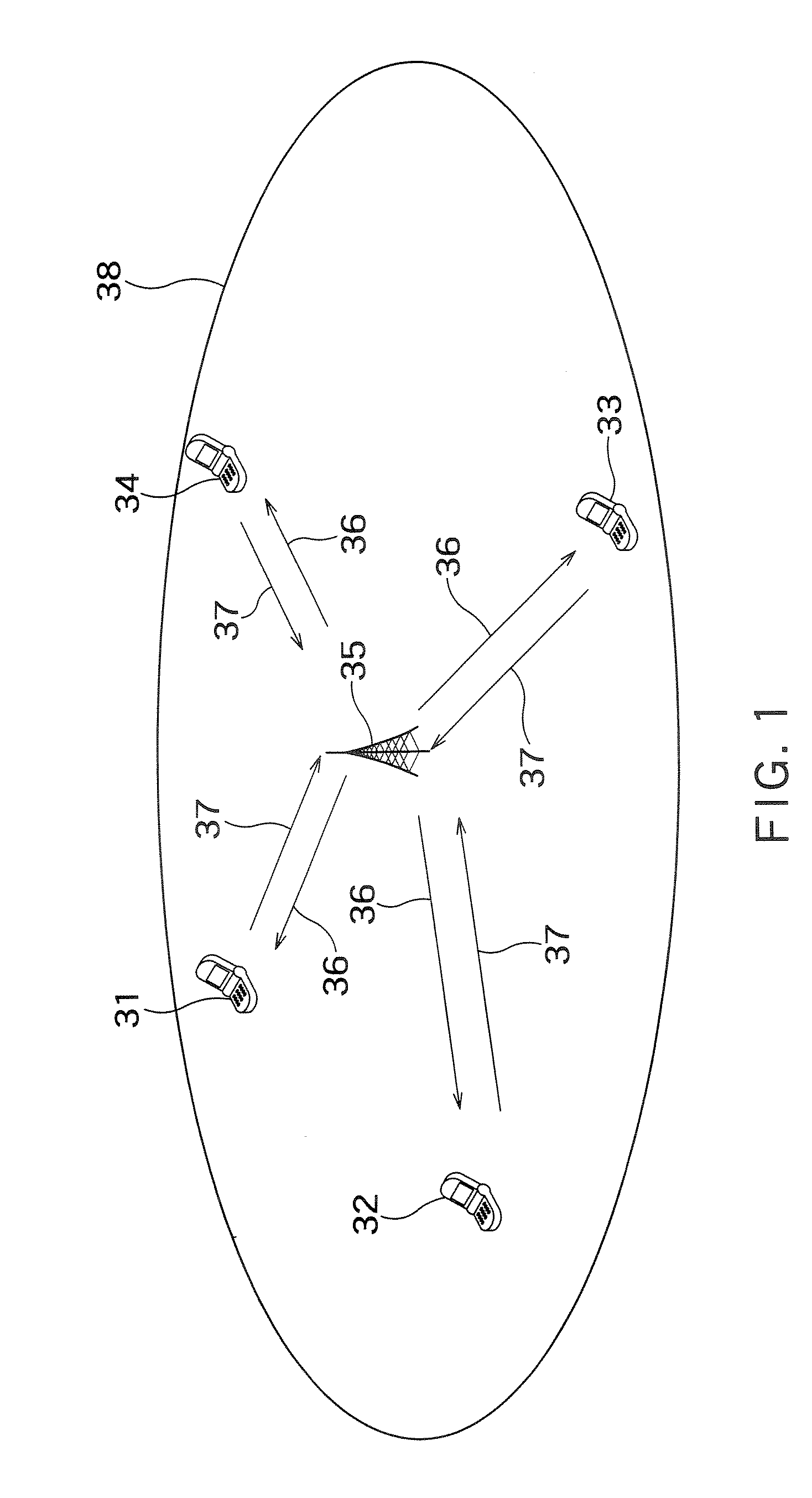
[0043]FIG. 1 shows an example of a radio communication system according to this embodiment. This radio communication system includes a base station 35 and a plurality of radio terminals (hereinafter simply referred to as “terminals”) 31, 32, 33 and 34. The terminal 31, terminal 32, terminal 33 and terminal 34 are located within reach of radio signals from the base station 35, that is, within a communication area (cell) 38. Suppose radio signal transmission from the base station 35 to the respective terminals 31 to 34 is called a “downlink 36” and radio signal transmission from the respective terminals 31 to 34 to the base station 35 is called an “uplink 37.”

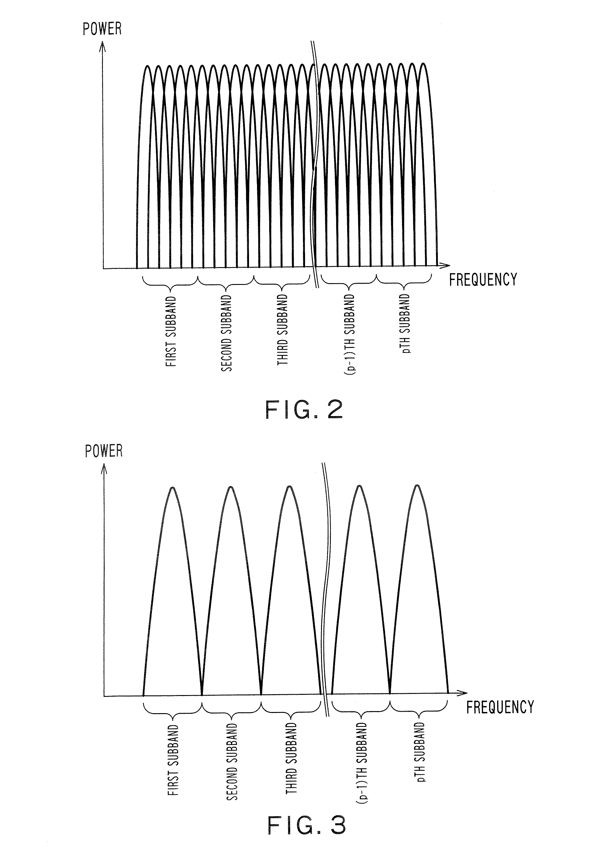
[0044]Suppose a multicarrier communication scheme such as OFDM (Orthogonal Frequency Division Multiplexing) or multicarrier CDMA (Code Division Multiple Access) is used for the downlink 36. In a multicarrier communication, communication is carried out using a plurality of subcarriers arranged on a frequency domain. An OFDM commun...

second embodiment

[0105]This embodiment will explain CQI feedback by a terminal and scheduling by a base station in detail.

[0106]As explained in the first embodiment, FIG. 10 shows an example of a downlink frame format. One subband includes 15 subcarriers and one subframe includes seven OFDM symbols. The total number of subcarriers is 300 and the total number of subbands is 20. Furthermore, suppose one frame includes a plurality of subframes and assignment of subbands is updated on a frame boundary. Furthermore, suppose the number of subbands required by the terminal for the downlink is four. Suppose the hatching areas in the figure denote subframes to which pilot signals are assigned.

[0107]Furthermore, suppose a base station 35 is communicating with a terminal 31, terminal 32 and terminal 33. Furthermore, suppose the terminal 31 to terminal 33 are currently receiving an mth subframe determined as a CQI generation time. Therefore, each terminal performs channel estimation using pilot signals and furt...

third embodiment

[0117]This embodiment will explain an example of a method of generating CQIs.

[0118]The lower part of FIG. 15 indicates CQIs to be fed back from a terminal to a base station. The upper part of FIG. 15 indicates a reception power of each subband calculated by the terminal. Suppose the terminal sets priority in descending order of reception power. When four CQIs can be fed back simultaneously, CQIs that are fed back first are CQI5, CQI4, CQI13 and CQI3. These CQIs correspond to CQIs of the four frequency channels (Y frequency channels) with high priority.

[0119]Suppose the next CQI to be fed back has quality obtained by averaging communication quality of a plurality of subbands (X frequency channels). For example, suppose each CQI fed back for the second time includes average communication quality obtained by averaging communication quality of two subbands. As a result, it is possible to feed back communication quality corresponding to a total of 8 (=2×4) subbands in the second feedback...


PUM


Abstract

There is provided with a radio terminal which is assigned one or more frequency channel to carry out downlink communication with a base station, including: a reception unit configured to receive signals of a plurality of frequency channels from the base station; a quality measuring unit configured to measure communication quality of each frequency channel; a priority setting unit configured to set priority for each frequency channel; a transmission unit configured to transmit communication quality information indicating communication quality of each frequency channel in descending order of priority to the base station; and a control unit configured to provide a signal instructing to stop transmission of the communication quality information to the transmission unit upon receiving a transmission stop instruction for instructing to stop transmission of the communication quality information from the base station.

Description

CROSS-REFERENCE TO RELATED APPLICATIONS[0001]This application is based upon and claims the benefit of priority from the prior Japanese Patent Applications No. 2006-95133 filed on Mar. 30, 2006, the entire contents of which are incorporated herein by reference.BACKGROUND OF THE INVENTION[0002]1. Field of the Invention[0003]The present invention relates to a base station, radio terminal and radio communication method.[0004]2. Related Art[0005]A communication scheme such as OFDM (Orthogonal Frequency Division Multiplexing) communication scheme or multicarrier CDMA (Code Division Multiple Access) communication scheme whereby digital signals are transmitted and received by being mapped to a plurality of subcarriers over wider bandwidth is attracting attention in recent years. These communication schemes make it possible to increase transmission rate and improve resistance to frequency selective fading. On the other hand, OFDMA (Orthogonal Frequency Division Multiple Access) which provide...

Claims


Application Information

Patent Timeline
Patent Type & Authority Applications(United States)
IPC IPC(8): H04B7/00H04Q7/20H04W72/08
CPCH04L1/0026H04L1/0027H04L1/0029H04L5/0007H04W72/10H04L25/0224H04W72/0406H04W72/085H04L5/006H04W72/542H04W72/20H04W72/56
Inventor SAKATA, REN
Owner KK TOSHIBA
Why Eureka
Try Eureka