
Polyaxial occipital plate

a technology of occipital plate and occipital plateau, which is applied in the field of medical devices, can solve the problems of occipital plate implant assembly, affecting the function and requiring long preparation time, so as to achieve the effect of reducing the stress on the atlantoaxial joint, reducing the risk of fracture, and reducing the use of the occipital pla

Inactive Publication Date: 2007-10-04
CUSTOM SPINE INC
View PDF23 Cites 76 Cited by
  • Summary
  • Abstract
  • Description
  • Claims
  • Application Information

AI Technical Summary

Problems solved by technology

The most simple, but generally most difficult, to use form is that of a rod that smoothly tapers to an occipital plate that must be bent and contoured to match highly varied anatomy.
All of these iterations have at most one to two degrees of freedom and typically require long preparation time to ensure a proper bend.
This makes the implants both difficult to connect to the longitudinal rod member and the occipital plateau without putting stress on the atlantoaxial joint.

Method used


Image

  • Polyaxial occipital plate
  • Polyaxial occipital plate
  • Polyaxial occipital plate

Examples


Embodiment Construction

[0040] The embodiments herein and the various features and advantageous details thereof are explained more fully with reference to the non-limiting embodiments that are illustrated in the accompanying drawings and detailed in the following description. Descriptions of well-known components and processing techniques are omitted so as to not unnecessarily obscure the embodiments herein. The examples used herein are intended merely to facilitate an understanding of ways in which the embodiments herein may be practiced and to further enable those of skill in the art to practice the embodiments herein. Accordingly, the examples should not be construed as limiting the scope of the embodiments herein.

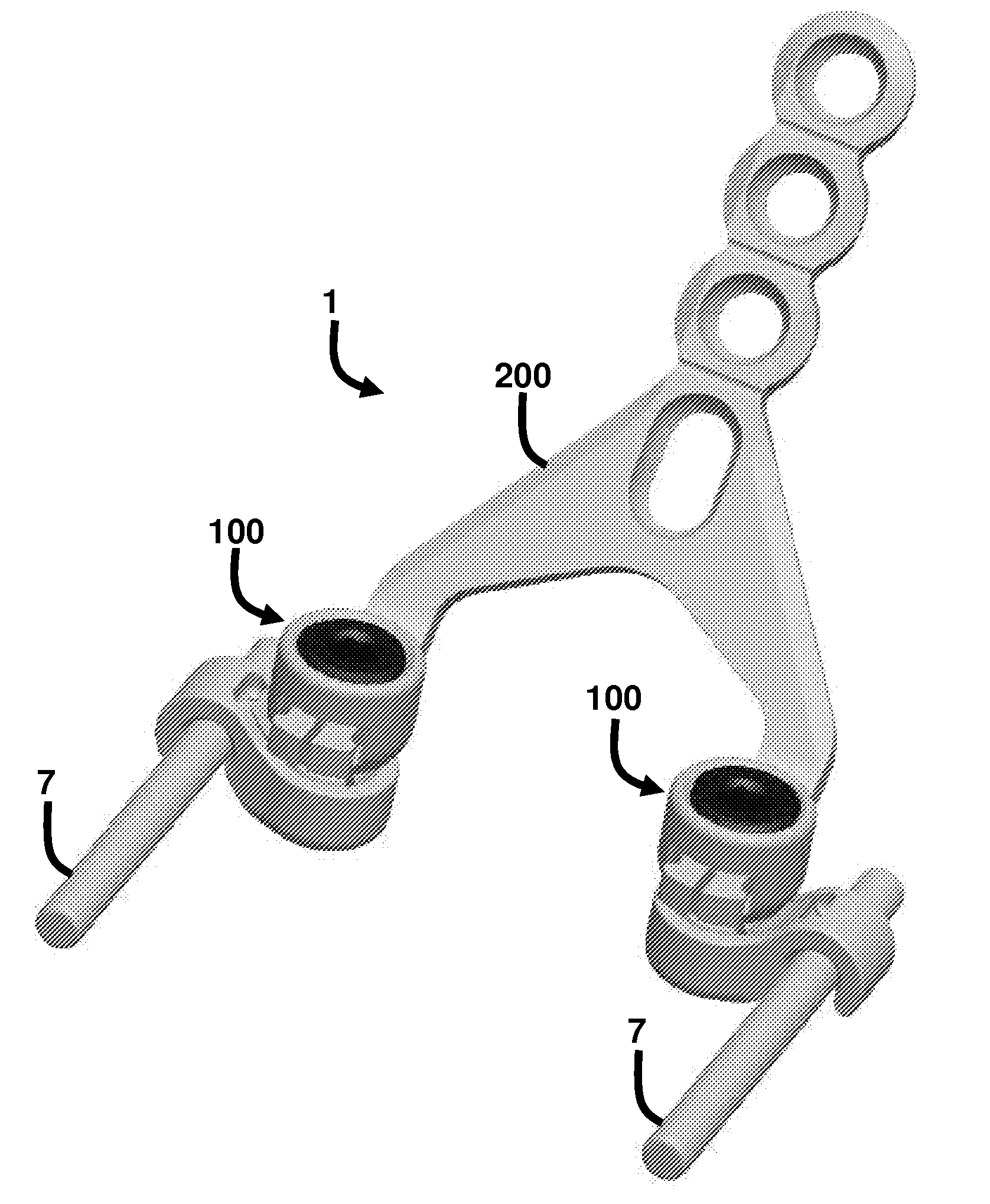
[0041] As mentioned, there remains a need for a new medical device that is a capable of connecting to the longitudinal members of a cervico-thoracic spinal fusion construct to an occipital plate providing improved ease of use. The embodiments herein achieve this by providing an easy to use po...


PUM


Abstract

A polyaxial occipital plate assembly and method comprises a longitudinal member; a polyaxial connector head; a socket portion adapted to retain the connector head; a flexible clip operatively connected to the socket portion and adapted to receive the longitudinal member; an occipital plate comprising clips operatively connected to the connector head; and a locking mechanism operatively connected to the connector head and the clips, wherein engagement of the locking mechanism to the connector head causes the clips to lock into the connector head and outwardly expand the connector head thereby causing the flexible clip to squeeze against the longitudinal member. The plate comprises a pair of opposed legs comprising the clips attached to ends of the legs; a body portion operatively connected to the pair of opposed legs, wherein the body portion is positioned at any of an obtuse and an acute angle relative to the pair of opposed legs.

Description

CROSS-REFERENCE TO RELATED APPLICATIONS [0001] This application is a continuation-in-part (CIP) of U.S. patent Ser. No. 11 / 567,380, filed on Dec. 6, 2006 and entitled “Spinal Cross-Connector,” (hereinafter “the '380 cross-connector”) and assigned to Custom Spine, Inc. of Parsippany, N.J., which is a CIP of U.S. patent Ser. No. 11 / 373,386, filed on Mar. 10, 2006 and entitled “Spinal Cross-Connector,” (hereinafter “the '386 cross-connector”) and assigned to Custom Spine, Inc. of Parsippany, N.J., the complete disclosures of which, in their entireties, are herein incorporated by reference.BACKGROUND [0002] 1. Technical Field [0003] The embodiments herein generally relate to medical devices, and, more particularly, to occipital plate implant assemblies. [0004] 2. Description of the Related Art [0005] There are many occipital plate implants on the market today. Some implants have through-holes and must be preloaded on the rod. Others have top loading sockets similar to polyaxial screws w...

Claims


Application Information

Patent Timeline
IPC IPC(8): A61F2/30
CPCA61B17/7055A61B17/7044
Inventor MARKWORTH, AARON D.
Owner CUSTOM SPINE INC
Features
  • Generate Ideas
  • Intellectual Property
  • Life Sciences
  • Materials
  • Tech Scout
  • Unparalleled Data Quality
  • Higher Quality Content
  • 60% Fewer Hallucinations
Learn More