Apparatus And Method For Friction Stir Spot Welding

a friction stir and spot welding technology, applied in the field of welding, can solve the problems of material plasticization and weld formation, inability to yield satisfactory welds, etc., and achieve the effect of reducing or eliminating at least some of the disadvantages and problems

Inactive Publication Date: 2007-10-18
SOUTHERN METHODIST UNIVERSITY
View PDF4 Cites 45 Cited by
  • Summary
  • Abstract
  • Description
  • Claims
  • Application Information

AI Technical Summary

Benefits of technology

[0003] The present invention provides an apparatus and method for spot welding that substantially reduces

Problems solved by technology

Friction between the shoulder and the workpiece heats the material, causing the material to plasticiz

Method used


Image

  • Apparatus And Method For Friction Stir Spot Welding
  • Apparatus And Method For Friction Stir Spot Welding
  • Apparatus And Method For Friction Stir Spot Welding

Examples


Embodiment Construction

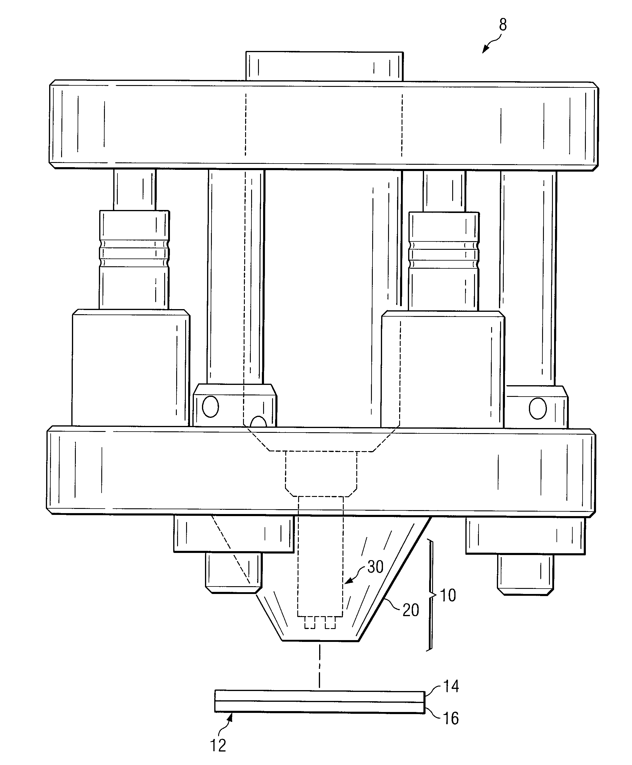
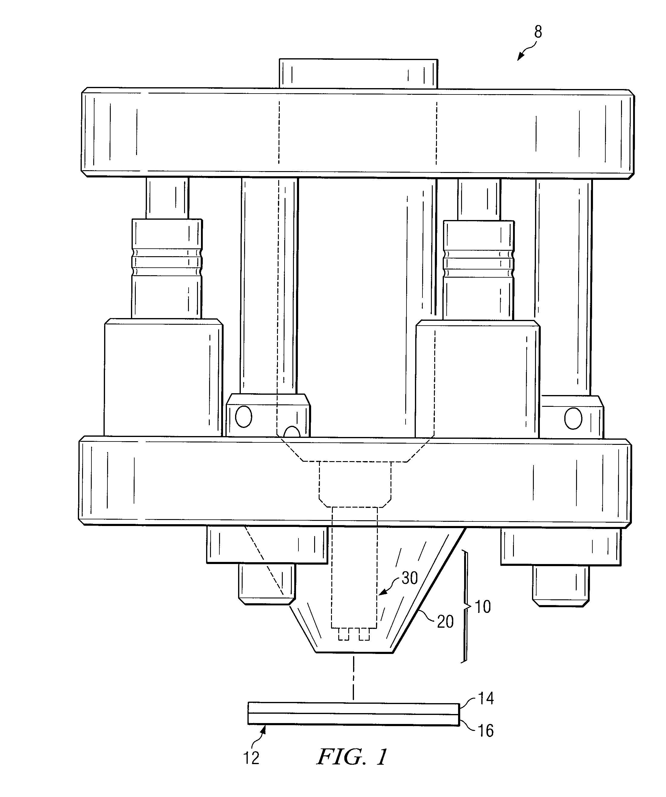
[0015]FIG. 1 is an illustration of a welding system 8 for friction stir spot welding that may be used to weld a workpiece 12, in accordance with an embodiment of the invention. Welding system 8 includes a welding apparatus 10 with a welding head 20 and a rotating tool 30 coupled as shown.

[0016] According to one embodiment of operation, welding apparatus 10 moves towards workpiece 12 until off-center protrusions of rotating tool 30 penetrate workpiece 12. The off-center protrusions stir the material of workpiece 12, while rotating tool 30, other parts of welding apparatus 10, and workpiece 12 contain displaced material to form a spot weld. The off-center protrusions may increase the contact area between rotating tool 30 and the workpiece 12, which may allow for faster plasticization of the workpiece material.

[0017] In the illustrated embodiment, workpiece 12 may represent any suitable workpiece that may be joined by friction stir spot welding. For example, workpiece 12 may represen...


PUM

PropertyMeasurementUnit
Forceaaaaaaaaaa
Pressureaaaaaaaaaa
Frictionaaaaaaaaaa

Abstract

An apparatus for welding a workpiece has a welding head and a rotating tool. The welding head has a recessed portion and a welding head end to be placed in contact with a surface of the workpiece. The rotating tool is disposed within the recessed portion of the welding head. The rotating tool is operable to rotate about an axis and to translate along the axis. The rotating tool comprises a rotating tool end to be placed in contact with material of the workpiece. The rotating tool end comprises a shoulder and one or more off-center protrusions. The shoulder has a surface operable to frictionally heat the material of the workpiece. An off-center protrusion is operable to penetrate and displace the material of the workpiece to form a weld.

Description

TECHNICAL FIELD [0001] This invention relates in general to welding and, more particularly, to an apparatus and a method for friction stir spot welding. BACKGROUND [0002] Welding systems are used to join parts of a workpiece. Known friction stir spot welding (FSSW) systems use a rotating tool to join workpiece parts. The rotating tool includes a pin centered on a shoulder. As the tool rotates, the pin penetrates the material of the workpiece, while the shoulder comes in contact with the workpiece. Friction between the shoulder and the workpiece heats the material, causing the material to plasticize and form a weld. These known systems, however, do not yield satisfactory welds in certain situations. SUMMARY OF THE DISCLOSURE [0003] The present invention provides an apparatus and method for spot welding that substantially reduces or eliminates at least some of the disadvantages and problems associated with previous methods and systems. [0004] In accordance with some embodiments, an ap...

Claims


Application Information

Patent Timeline
IPC IPC(8): B23K20/12B23K37/00
CPCB23K20/123B23K20/1255B23K20/126B23K2203/10B23K37/0235B23K2201/18B23K20/1265B23K2101/18B23K2103/10
Inventor VALANT, MICHAEL E.KOVACEVIC, RADOVAN
Owner SOUTHERN METHODIST UNIVERSITY
Why Eureka
Try Eureka