Offset valve system for downhole drillable equipment

a valve system and drillable technology, applied in the direction of drilling casings, drilling pipes, borehole/well accessories, etc., can solve the problems of difficult to prevent the valve mechanism from spinning, large problems, and unsatisfactory results

Inactive Publication Date: 2007-10-25
BAKER HUGHES INC
View PDF22 Cites 30 Cited by
  • Summary
  • Abstract
  • Description
  • Claims
  • Application Information

AI Technical Summary

Benefits of technology

[0013] Float equipment is constructed to have the check valve in an offset and / or skewed position with respect to the centerline of the tubular housing that is part of a string. The design is applicable to poppet type check valves as well as flapper type valves that are actuated with a flow tube. The off center and / or skewed position of the valve components allows the cutting structure on a drill bit, rather than the nozzle area on the bit bottom to make intimate contact with the valve components to accelerate the milling out of the assembly and the making of additional hole beyond the recently cemented string.

Problems solved by technology

These valve mechanisms are normally placed in the center of the well and can create great problems when they are milled or drilled up at a later stage to deepen the wellbore.
Also, since the valve mechanism is in the center of the borehole, it makes it difficult to prevent the valve mechanisms from spinning.
Either option is not ideal.

Method used


Image

  • Offset valve system for downhole drillable equipment
  • Offset valve system for downhole drillable equipment
  • Offset valve system for downhole drillable equipment

Examples


Embodiment Construction

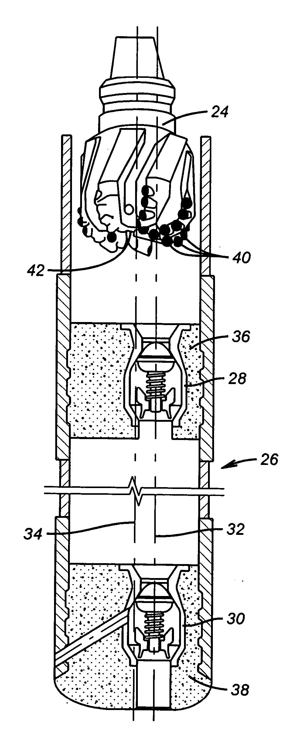
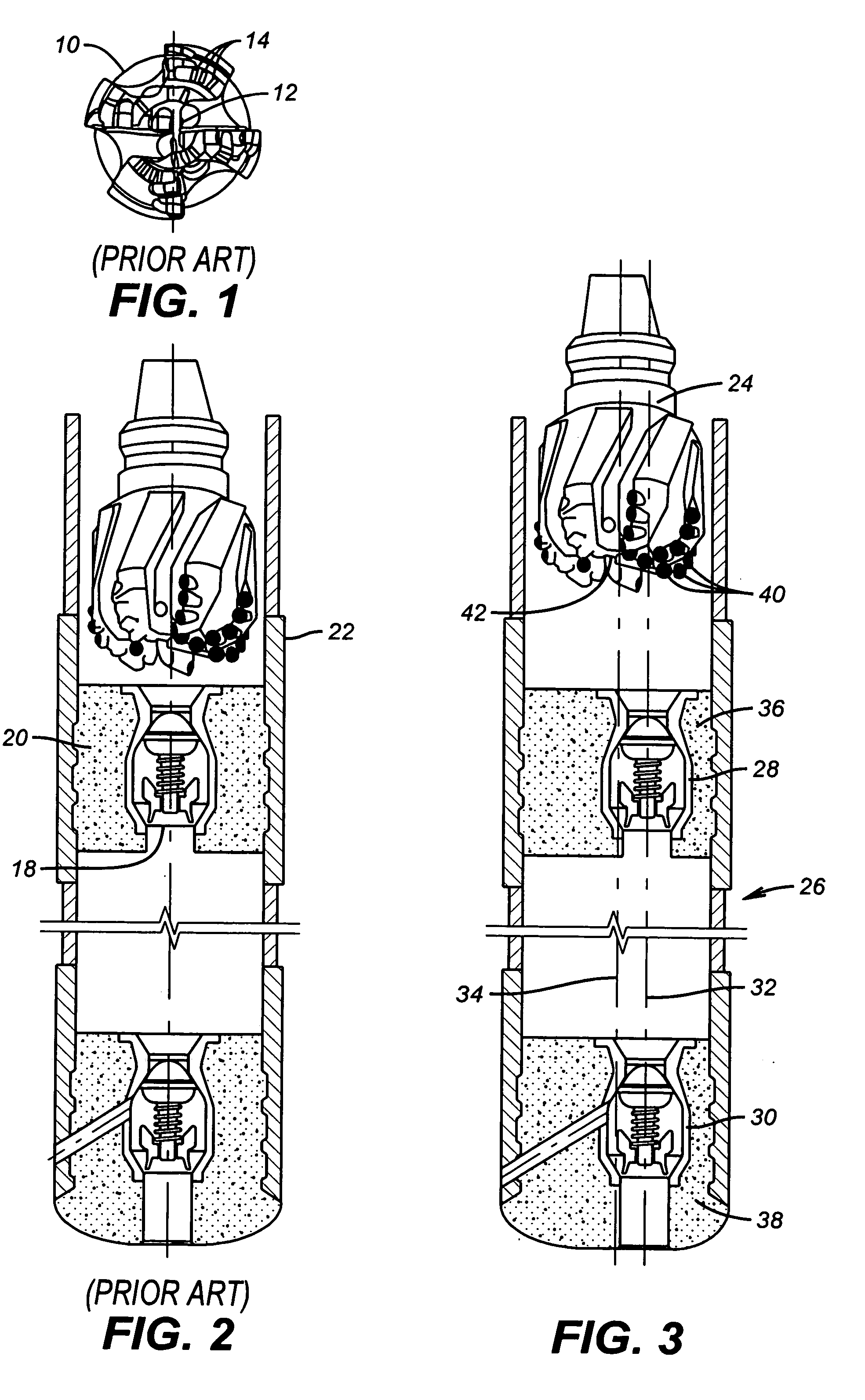
[0020]FIG. 3 shows a bit 24 just above a shoe track 26 which comprises poppet type valves 28 in a float collar and 30 in a float shoe of a typical shoe track 32 which is offset from centerline 34 of the shoe 26. Valves 28 and 30 can also be on different centerlines from each other while both are offset radially from the centerline 34 of the shoe 26. Cement (or any type of drillable material) 36 and 38 respectively surrounds valves 28 and 30 for support in the shoe track 26. As an alternate to cement, other common drillable materials used in the oil industry can be used.

[0021] The bit 24 has bottom details similar to those shown in FIG. 1. It can be a polycrystalline diamond bit, a rock bit or a tapered or flat bottom mill.

[0022] Because the valves 28 and 30 are offset from centerline 34 the inserts 40 dig directly at the valve assemblies as opposed to having the nozzles 42 that are generally in the center of the bit align with valves 28 and 30 which makes them harder to mill out. ...


PUM


Abstract

Float equipment is constructed to have the check valve in an offset and / or skewed position with respect to the centerline of the tubular housing that is part of a string. The design is applicable to poppet type check valves as well as flapper type valves that are actuated with a flow tube. The off center and / or skewed position of the valve components allows the cutting structure on a drill bit, rather than the nozzle area on the bit bottom to make intimate contact with the valve components to accelerate the milling one of the assembly and the making of additional hole beyond the recently cemented string.

Description

FIELD OF THE INVENTION [0001] The field of this invention is downhole equipment destined to be milled out after use and more particularly the positioning of the movable components within a surrounding tubular to speed up milling and even more specifically in a cementing application to obtain improved cement distribution while minimizing drilling fluid entrainment which can adversely affect the quality of the cement seal in the surrounding annulus. BACKGROUND OF THE INVENTION [0002] Float Equipment or an Auto-fill Collar is normally run at the bottom of a casing or tubing string to halt cement displacement. The short tubular section between the shoe and float collar is called the shoe track and is provided as a buffer within the casing to retain contamination that may build up ahead of the displacement plugs. The length of the shoe track is adjusted accommodating to well conditions. [0003] The float shoe can prevent reverse flow, or U-tubing, of cement slurry from the annulus into th...

Claims


Application Information

Patent Timeline
Patent Type & Authority Applications(United States)
IPC IPC(8): E21B33/14E21B17/14E21B29/00
CPCE21B21/10E21B33/14E21B33/1204
Inventor KRAUSS, CHRISTIAANROSENBLATT, STEVE
Owner BAKER HUGHES INC
Why Eureka
Try Eureka