Motorized swing bolt lock

a technology of swing bolts and locking pins, which is applied in the direction of safes, mechanical devices, fastening means, etc., can solve the problems of unfavorable retraction of locking pins, and achieve the effect of preventing jolts or shocks, and preventing linear movement of slide bars

Active Publication Date: 2007-11-01
DORMAKABA USA INC
View PDF5 Cites 20 Cited by
  • Summary
  • Abstract
  • Description
  • Claims
  • Application Information

AI Technical Summary

Benefits of technology

[0008]The slide bar is retained in a locked position by the torsion member. An arm of the torsion member is biased upwardly to engage a tab of the slide bar. Engagement with the tab prevents linear movement of the slide bar.
[0009]The arm is engaged to a clutch driven by an electric motor. The clutch includes an eccentric outer portion that moves the arm downwardly to release the slide bar and allow linear movement responsive to rotation of the swing bolt. Bias in the torsion member provided by the securement of the leg prevents jolts or shocks from freeing the slide bar from the locked position.
[0010]Accordingly, the example lock mechanism provides the desired securement of the swing bolt in a mechanism that is not defeatable by vibrations, shocks or jolts and that provides protection to the electric motor.

Problems solved by technology

Disadvantageously, linear movement of the locking pin can be susceptible to external shocks and vibrations that can cause undesired retraction of the locking pin.

Method used


Image

  • Motorized swing bolt lock
  • Motorized swing bolt lock
  • Motorized swing bolt lock

Examples


Embodiment Construction

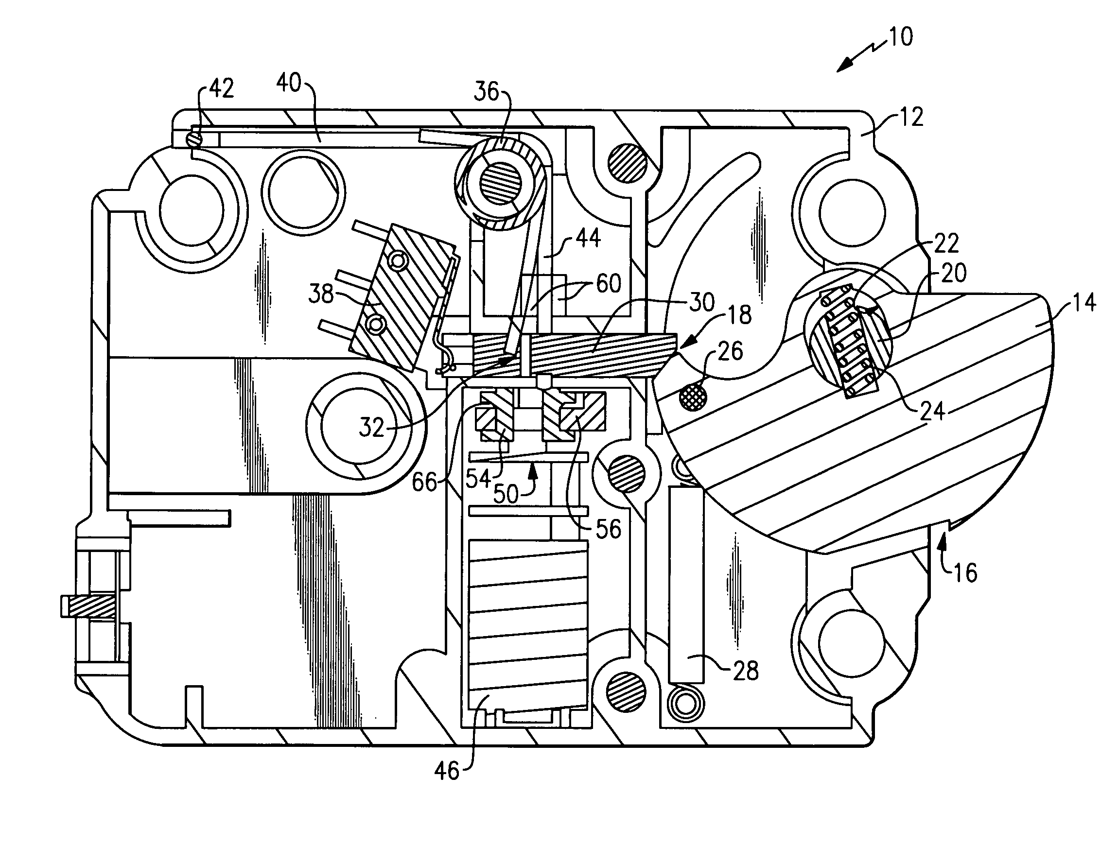
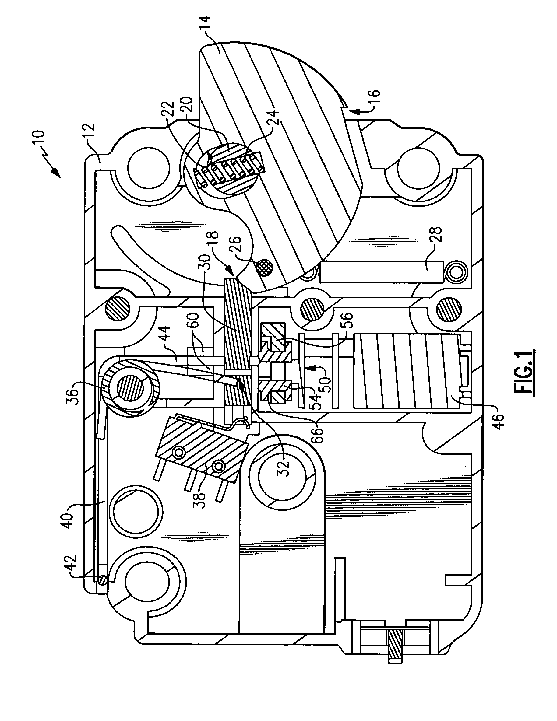
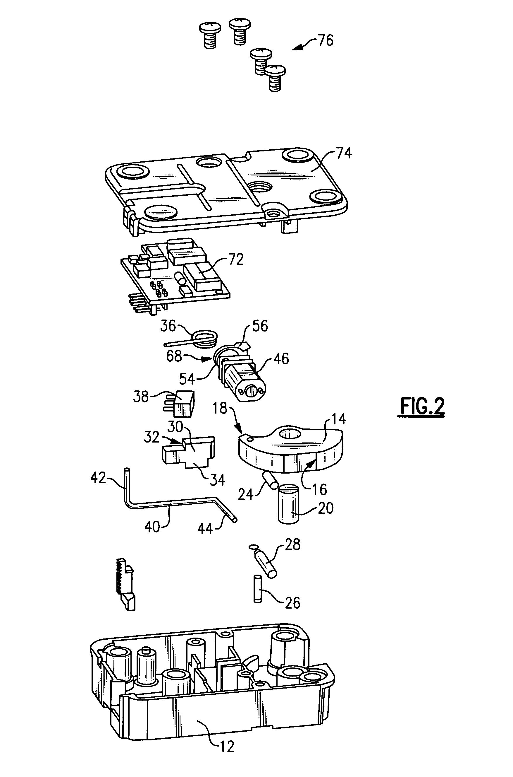
[0018]Referring to FIG. 1, an example lock mechanism 10 includes a housing 12 that supports rotation of a swing bolt 14 about a pivot pin 20. The swing bolt 14 includes an eccentric opening 22 within which pivot pin 20 is disposed. The eccentric opening 22 provides for linear movement of the swing bolt 14 in a direction parallel with a bias spring 24. The bias spring 24 biases the swing bolt 14 to provide rotary motion of the swing bolt 14 about the pivot pin 20 when released from a locked position.

[0019]The swing bolt 14 includes an abutment 18 that engages a slide bar 30. The slide bar 30 is biased into engagement with the swing bolt 14 by biasing spring 36. The slide bar 30 is movable linearly away from the swing bolt 14 to allow rotation of the swing bolt 14 to an unlocked position. Attempted rotation of the swing bolt 14 with the slide bar 30 engaged causes linear movement of the swing bolt 14 substantially parallel with the bias spring 24 such that a hook 16 of the swing bolt ...


PUM


Abstract

A lock mechanism includes a torsion bar that prevents movement of a slide bar abutting a swing bolt. The torsion bar engages the swing bar in a direction transverse to sliding movement to prevent undesired movement away from abutting contact with the swing bolt.

Description

CROSS REFERENCE TO RELATED APPLICATION[0001]The application claims priority to U.S. Provisional Application No. 60 / 791,386 which was filed on Apr. 12, 2006.BACKGROUND OF THE INVENTION[0002]This invention generally relates to a swing bolt lock. More particularly, this invention relates to a locking and unlocking mechanism for a swing bolt lock.[0003]Doors of safes, vaults or other security enclosures include a bolt that moves from a locked to a non-locked position responsive to a lock mechanism. A swing bolt locking device includes a substantially D-shaped bolt that rotates about a pivot. The D-shaped bolt includes an abutment that contacts a slide bar. The slide bar is typically locked in a position that prevents movement of the D-shaped bolt to provide a desired locked condition. The slide bar is typically locked by a pin that is movable through an opening by a solenoid. Energizing the solenoid retracts the pin and allows movement of the slide bar that in turn allows unlocking of t...

Claims


Application Information

Patent Timeline
Patent Type & Authority Applications(United States)
IPC IPC(8): E05C3/06
CPCE05B17/2092E05B47/0012E05B47/0603E05B63/0013E05B2015/0455E05B2015/0496E05G1/04E05B2047/0026E05B2047/0031E05B2047/0069E05B2047/0074E05B2047/0093E05B2047/0024Y10T292/0913Y10T292/1082Y10T292/1091
Inventor MOON, CHARLES W.WRIGHT, MICHAEL J.
Owner DORMAKABA USA INC
Why Eureka
Try Eureka