
Positive locking connector for vehicle component

Inactive Publication Date: 2009-03-03
SIEMENS VDO AUTOMOTIVE CORP
View PDF3 Cites 3 Cited by
  • Summary
  • Abstract
  • Description
  • Claims
  • Application Information

AI Technical Summary

Benefits of technology

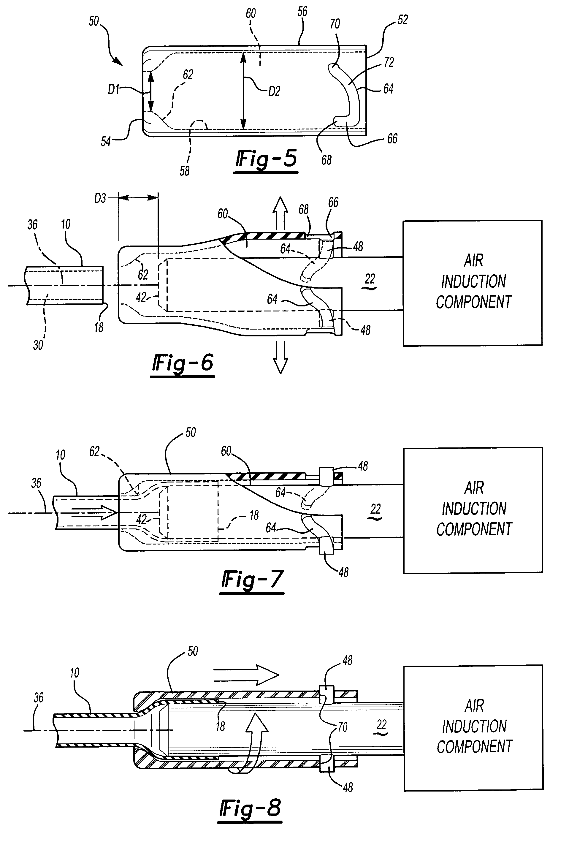
[0012]In one disclosed embodiment, the connector assembly is used to interconnect a hose end to a vehicle component such as an intake manifold induction component or other similar component. Preferably, the retention member is a locking cap that is made from a resilient or flexible material such as glass filled nylon. The locking cap is compressed and slid over the projection prior to the hose being installed onto the projection. The locking cap is then released so that it assumes its original configuration. Once the cap has returned to its origi

Problems solved by technology

Due to the complexity of certain vehicle components, requiring barbs to be added to the nipples increases the complexity and cost of the injection molding tooling.
Also, the injection mold tooling that is used to form the barbs can wear over time, resulting in a softened barb profile.
This decreases the retention force connection between the nipple and the hose and can result in hose separation.
For example, during vehicle operation, the hoses are subject to vibrations and can be shaken loose due to the reduced retention force.
Or, if the vehicle is being serviced, a technician may bump or knock the hose loose due to the reduced retention force.
Another disadvantage with the barb retention feature is the potential for increased leakage.
If the barbs are formed near the insertion end of the nipple, an increased installation load is required, which can tear or gouge the inner surface of the hose, creating a potential leak path.
Further, if a sufficient installation load is not applied then the hose may not achieve an adequate engagement length, which also increases leak potential.
The potential for leaking is also increased by the injection molding process itself.
This results in the formation of a parting line on the nipple.
After installation, the parting line provides a potential leak path.

Method used


Image

  • Positive locking connector for vehicle component
  • Positive locking connector for vehicle component
  • Positive locking connector for vehicle component

Examples


Embodiment Construction

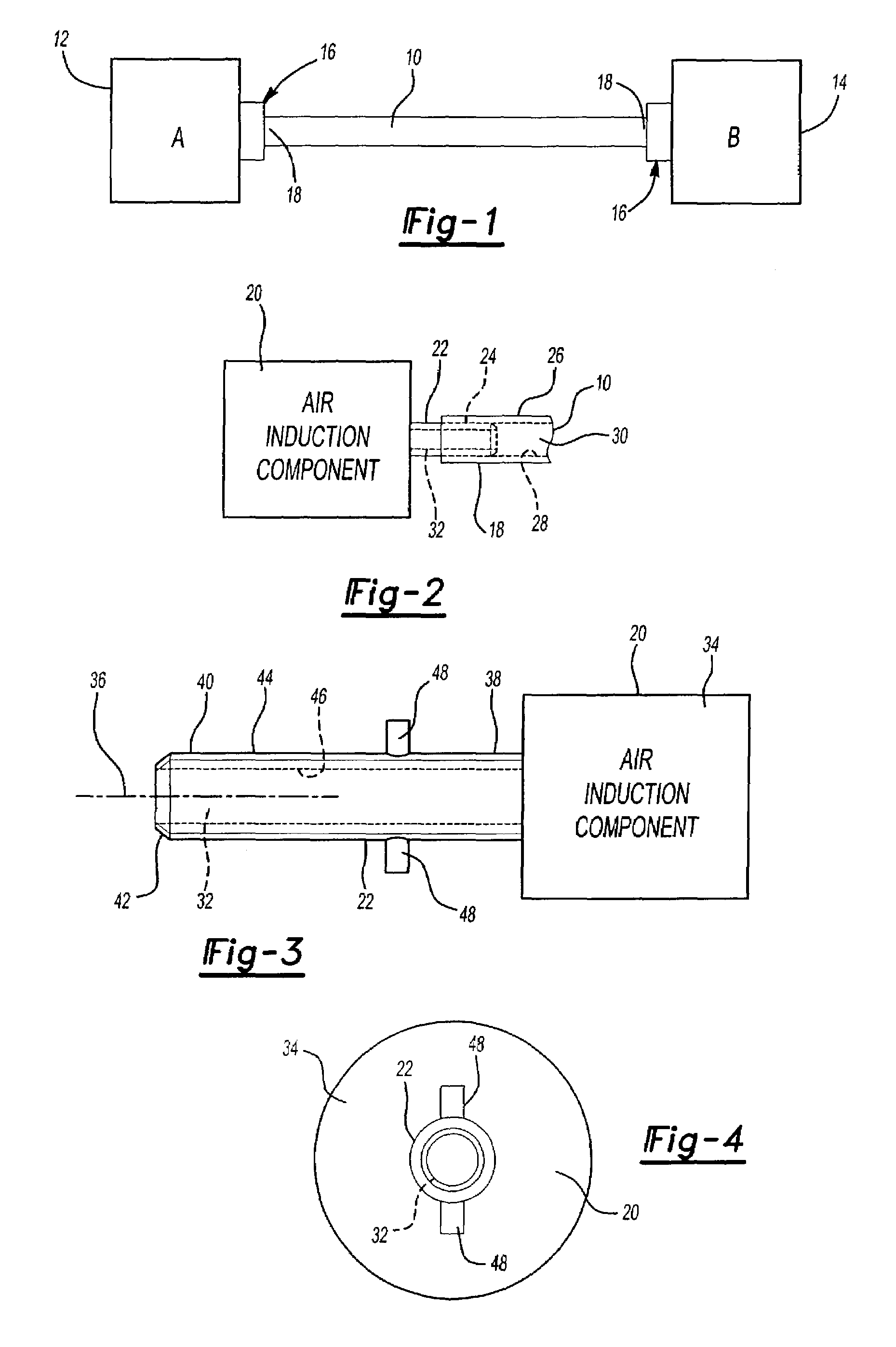
[0024]A hose 10 is used to interconnect a first vehicle component 12 to a second vehicle component 14. A positive locking connector assembly, shown generally at 16, is used to securely align, attach, and lock each hose end 18 to the respective first 12 and second 14 vehicle components. The connector assembly 16 is movable between an unlocked position where the hose end 18 can be removed from the vehicle component 12, 14 and a locked position where the hose end 18 is prevented from being removed from the vehicle component 12, 14, thus providing a serviceable connection.

[0025]Any type of vehicle component requiring a hose connection can utilize this unique positive locking connector assembly 16. The hose 10 provides fluid communication between various vehicle systems and can be configured to conduct air, hydraulic fluid, brake fluid, emission gases, etc. Thus, emission components, brake components, air induction components, intake manifold components, fuel components, etc., which requ...


PUM

PropertyMeasurementUnit
Forceaaaaaaaaaa
Diameteraaaaaaaaaa
Resilienceaaaaaaaaaa

Abstract

A vehicle connector assembly includes a positive lock feature that allows a hose to be quickly and easily attached to a vehicle component such as an intake manifold or air induction component. The component includes a projection that extends outwardly from a main body to a distal end. A locking cap is installed over the projection and cooperates with an alignment feature on the projection such that the cap does not separate from the projection prior to installation of the hose. An end of the hose is slidably installed within the locking cap and over the projection. The locking cap is then rotated from an unlocked position to a locked position to prevent linear movement of the hose relative to the projection. The locking cap is made from a resilient material and provides a serviceable connection.

Description

CROSS-REFERENCE TO RELATED APPLICATIONS[0001]The application claims priority to U.S. Provisional Application No. 60 / 374,399, which was filed on Apr. 22, 2002.BACKGROUND OF THE INVENTION[0002]This invention relates to a vehicle connector assembly that includes a locking member that aligns and locks a hose end to a vehicle component.[0003]Hoses are installed onto vehicle components such as an intake manifold, air induction, brake booster, and / or emission component. Typically, these vehicle components include nipples that extend outwardly from a main body of the component to a distal end. An end of the hose is slidably received over the distal end to engage the nipple in an interference fit to connect the hose to the component.[0004]The hose and nipple connection must remain secure throughout the life of the vehicle. In certain applications, such as for a brake booster connection or emission connection, the connection must meet safety and emission requirements. A retention feature is i...

Claims


Application Information

Patent Timeline
IPC IPC(8): F16L55/00F16L37/248
CPCF16L37/248Y10T403/253
Inventor POWELL, JEFFREY J.BRACKETT, STEPHEN E.
Owner SIEMENS VDO AUTOMOTIVE CORP
Learn More