Panel lock for electronic, electrical or control cabinets

a technology for electronic, electrical or control cabinets, applied in the field of panels, can solve the problem that there is no design that generally encompasses all of the desired characteristics, and achieve the effect of reducing shock exposur

Inactive Publication Date: 2007-03-29
COMPX INTERNATIONAL
View PDF26 Cites 0 Cited by
  • Summary
  • Abstract
  • Description
  • Claims
  • Application Information

AI Technical Summary

Benefits of technology

[0028] Various additional present aspects may be further optionally or alternatively practiced to create still further present exemplary panel lock assemblies. For example, in the foregoing exemplary panel lock assembly, the elongated housing portion may be configured to include a pair of frictionally engaging retaining elements on one end thereof. At the same time, or further alternatively, the slide element may include a recessed portion thereof which may be accessed via the window opening of the elongated housing portion to effect linear movement of the slide element. Such slide element may further include a pair of safety side wing elements for shielding such as a user's finger received in the recessed portion thereof from projecting into the interior of an associated enclosure.
[0029] Still further, the foregoing exemplary slide element engageable opening is preferably a generally keyhole-shaped, and the at least one protrusion of the rotatable plug assembly includes a pair of D-shaped protrusions, engageable in one orientation with said such slide element engageable opening so as to prevent linear movement of the slide element which consequently prevents engagement of such slide element at least one engagement tip engaging a locking bar of an associated enclosure, and engageable in another orientation with such slide element engageable opening so as to permit linear movement of such slide element which consequently permits engagement of the slide element at least one engagement tip engaging a locking bar of an associated enclosure.
[0030] Still further, an associated enclosure may be comprised of one of an electrical and non-electrically associated enclosures, and the elongated housing portion, the bottom housing portion, and the slide element may preferably all be comprised of non-conductive materials to reduce shock exposure from any energized electrical components otherwise residing with an associated enclosure.

Problems solved by technology

While various implementations of panel locks have been developed, no design has emerged that generally encompasses all of the desired characteristics as hereafter presented in accordance with the subject technology.

Method used


Image

  • Panel lock for electronic, electrical or control cabinets
  • Panel lock for electronic, electrical or control cabinets
  • Panel lock for electronic, electrical or control cabinets

Examples


Embodiment Construction

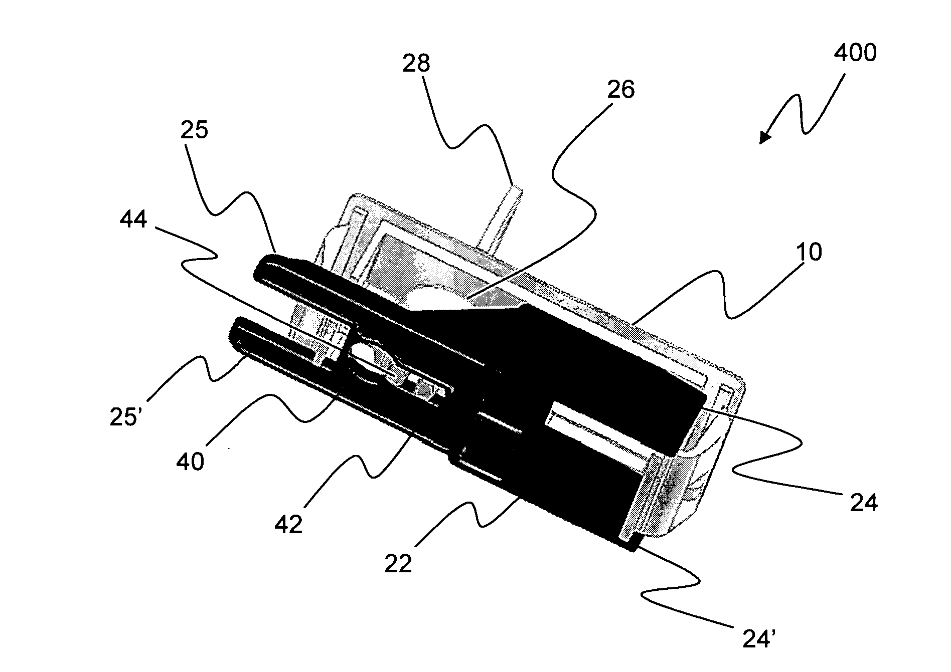
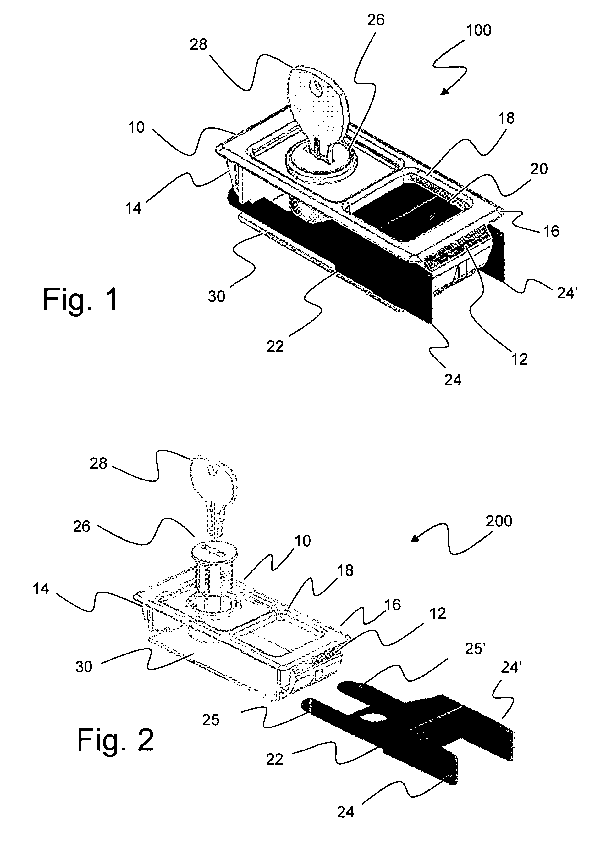
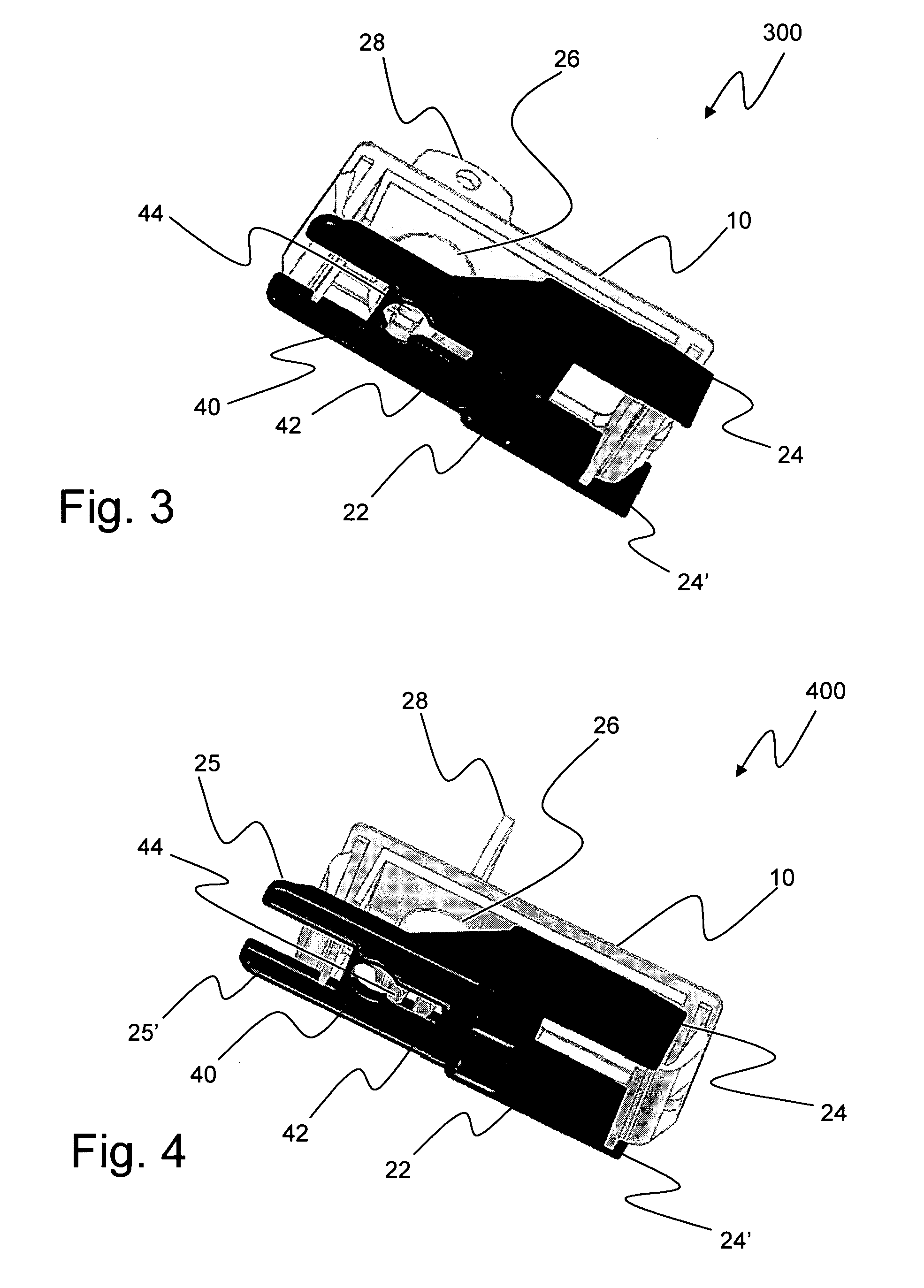
[0039] As discussed in the Summary of the Invention section, the present subject matter is particularly concerned with panel locks for use with a locking bar system but also encompasses closable enclosures that incorporate such panel locks.

[0040] Selected combinations of aspects of the disclosed technology correspond to a plurality of different embodiments of the present subject matter. It should be noted that each of the exemplary embodiments presented and discussed herein should not insinuate limitations of the present subject matter. Features or steps illustrated or described as part of one embodiment may be used in combination with aspects of another embodiment to yield yet further embodiments. Additionally, certain features may be interchanged with similar devices or features not expressly mentioned which perform the same or similar functions.

[0041] Reference will now be made in detail to presently preferred embodiments of the subject panel lock assembly. Referring now to the...


PUM


Abstract

Disclosed is a lock assembly such as for use with enclosures and access panels. The lock assembly includes a keyhole shaped aperture in a slide portion of the locking assembly that cooperates with double-D shaped protrusions associated with a locking plug. In a locked position, the double-D shaped protrusions inhibit movement of the slide portion. In an unlocked position, the double-D shaped elements may enter a more narrow portion of the keyhole shaped aperture and permit movement of the slide. The slide is associated with additional features so that movement of the slide selectively inhibits or provides consequential movement of other elements that in turn respectively deny or create access to an enclosure.

Description

PRIORITY CLAIM [0001] This application claims the benefit of previously filed U.S. Provisional Patent Application entitled “PANEL LOCK FOR ELECTRONIC, ELECTRICAL OR CONTROL CABINETS,” assigned U.S. Ser. No. 60 / 721,761, filed Sep. 29, 2005, and which is incorporated herein by reference for all purposes.FIELD OF THE INVENTION [0002] The present subject matter relates to locks. More particularly, the present subject matter relates to a panel lock for use with a locking bar system, and to selectively closable enclosures incorporating such present panel lock subject matter. BACKGROUND OF THE INVENTION [0003] The incorporation of locking devices into access openings for enclosures of all types yields many practical advantages. In the case of electrical enclosures such as control cabinets or other enclosures housing electrical or electronic devices, restricted access may be essential for safety reasons as well as to respond to certain legal requirements placed by certain governmental entit...

Claims


Application Information

Patent Timeline
Patent Type & Authority Applications(United States)
IPC IPC(8): E05B65/06
CPCE05B13/002E05C1/04E05B65/02Y10S292/31Y10T292/1031Y10T70/577Y10T70/5761Y10T70/5319Y10T292/0976Y10T70/5195
Inventor DALTON, ROBERT E. JR.HESPRICH, DONALD N.
Owner COMPX INTERNATIONAL
Why Eureka
Try Eureka