Inter-MME handover in evolved communication systems

a communication system and inter-mme technology, applied in the field of inter-mme handover in evolved communication systems, can solve the problems of conflicting with existing 3gpp requirements, active user equipments running out of coverage, and no solution to this problem has yet been shown, and achieve the effect of lossless delivery

Inactive Publication Date: 2007-11-01
NOKIA CORP
View PDF2 Cites 70 Cited by
  • Summary
  • Abstract
  • Description
  • Claims
  • Application Information

AI Technical Summary

Benefits of technology

[0037] It is an advantage of the present invention that a concept for handovers between control plane entities, independently of the user plane entity (i.e., either maintaining or also changing the user plane entity) is provided.
[0038] With the embodiments of the present invention, it is advantageous that active mode handovers are feasible between control plane entities.
[0039] Further, it is advantageous that the thus presented handover procedures are controlled by access network nodes, i.e. that the access network has control over the handover.
[0040] Further, it is advantageous that the core network is not involved in the handover preparation phase.
[0041] Further, it is advantageous that a lossless delivery is achieved by using a forwarding from one base station entity to the next base station entity, and that the user plane is switched only after a handover has been completed, i.e. late switching.
[0042] From an implementation point of view, it is beneficial that the embodiments of the present invention comply with existing standards and specifications.

Problems solved by technology

One important issue in the standardization of SAE / LTE systems are handover procedures.
This is however a disadvantage of this proposal in that active user equipments running out of coverage from the serving Node_B will have to go into an idle mode and reconnect to a new Node_B again afterwards.
This is a disadvantage thereof in that it conflicts with existing 3GPP requirements.
No solution to this problem has yet been shown in the art.
Another problem, which has not been addressed recently, is that a frequent transition between an active mode and an idle mode is expected and users are not expected to stay in active mode unless they really transfer data.

Method used


Image

  • Inter-MME handover in evolved communication systems
  • Inter-MME handover in evolved communication systems
  • Inter-MME handover in evolved communication systems

Examples


first embodiment

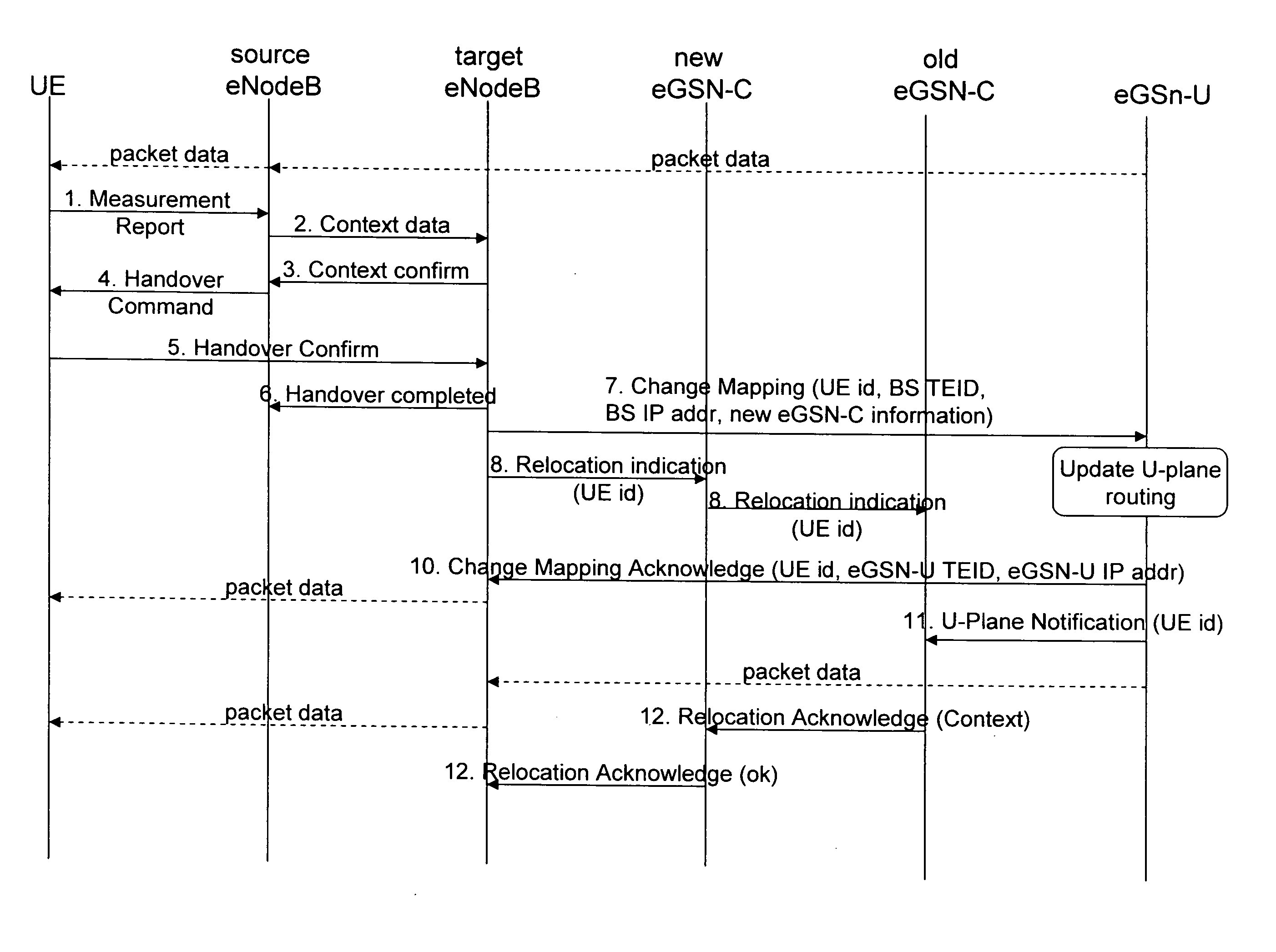
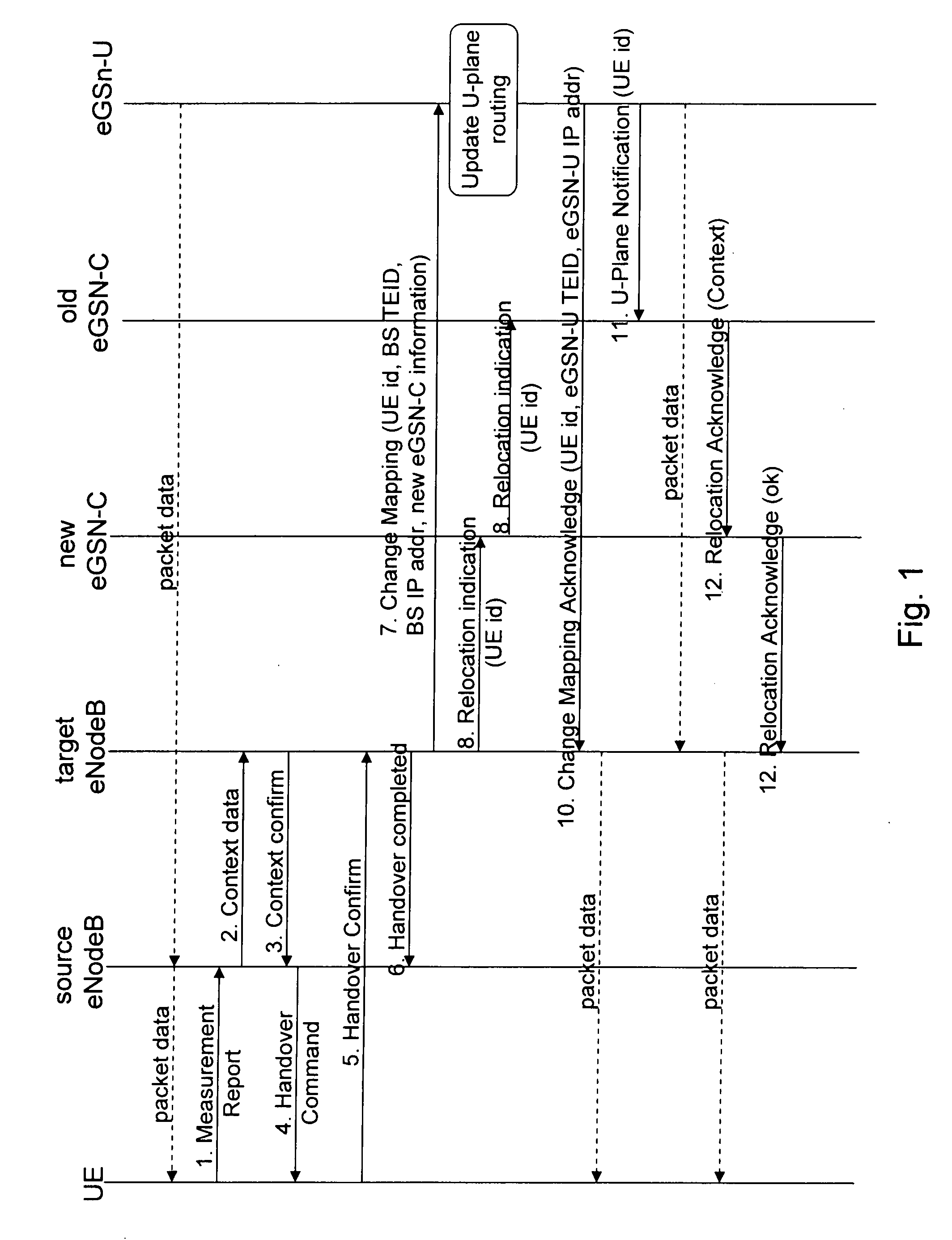
[0054]FIG. 1 shows a signaling diagram of a method according to the present invention. In detail, there is illustrated an inter-MME handover procedure, wherein the core network is not involved in handover preparation, wherein late switching and base station forwarding is used, and wherein path switching is effected directly from a target base station entity to a user plane entity.

[0055] In FIG. 1, steps 1 to 6 represent an access network handover between a source base station or eNodeB and a target base station or eNodeB. Such an intra-access system handover is as such known to a skilled person and will thus not be discussed in detail hereinafter.

[0056] The access network handover is completed by a respective message in step 6, which is sent from the target base station to the source base station. Upon this completion, the target base station of the access network decides on the need for a core network handover, i.e. an inter-MME handover. Such a decision is for example based on an...

second embodiment

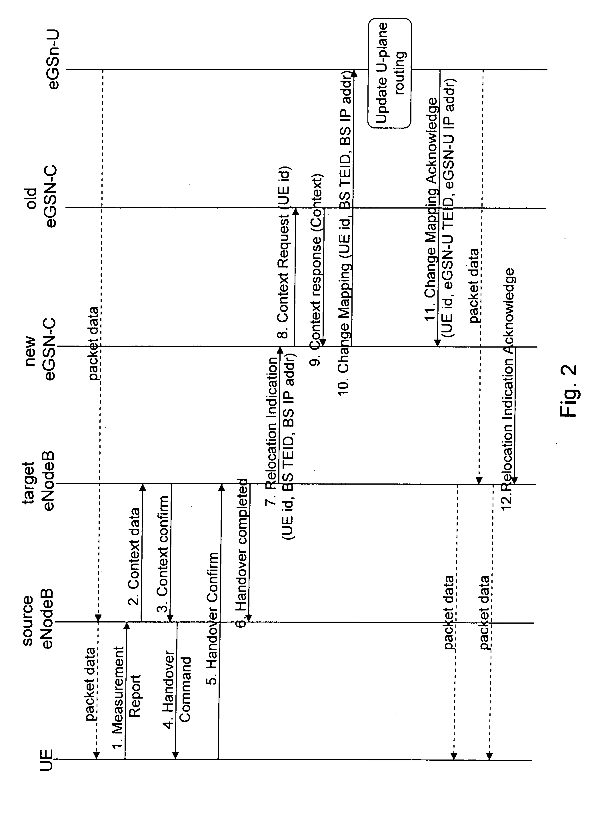
[0065]FIG. 2 shows a signaling diagram of a method according to the present invention. In detail, there is illustrated an inter-MME handover procedure, wherein the core network is not involved in handover preparation, wherein late switching and base station forwarding is used, and wherein path switching is effected from the target base station entity via the target control plane entity to the user plane entity.

[0066] As well as in FIG. 1, steps 1 to 6 of FIG. 2 represent an access network handover between a source base station or eNodeB and a target base station or eNodeB, the description of which will be omitted herein.

[0067] The completion of the access network handover, the decision on the need of a core network handover, the selection of a target control plane entity and the initiation of the core network handover by the target base station is similar to those as described in connection with the embodiment of FIG. 1.

[0068] The core network handover according to the present emb...

third embodiment

[0073]FIG. 3 shows a signaling diagram of a method according to the present invention. In detail, there is illustrated an inter-MME handover procedure, wherein the core network is not involved in handover preparation, wherein late switching and base station forwarding is used, and wherein path switching is effected from the target base station entity via the target control plane entity to the user plane entity.

[0074] The third embodiment may thus be regarded as an alternative to the second embodiment described above.

[0075] As well as in FIGS. 1 and 2, steps 1 to 6 of FIG. 3 represent an access network handover between a source base station or eNodeB and a target base station or eNodeB, the description of which will be omitted herein.

[0076] The completion of the access network handover, the decision on the need of a core network handover, the selection of a target control plane entity and the initiation of the core network handover by the target base station is similar to those as ...


PUM


Abstract

Measures for a handover in a communication system, the communication system comprising an access network having at least two base station entities and a core network having at least two control plane entities and at least one user plane entity, comprising the steps of initiating, upon completion of a radio network handover between a source base station entity and a target base station entity, a core network handover by the target base station entity, and performing the core network handover between a source control plane entity and a target control plane entity, wherein the user plane entity is maintained the same or changed.

Description

CROSS-REFERENCE TO RELATED APPLICATION [0001] This application claims priority of U.S. Provisional Patent Application Ser. No. 60 / 795,581, filed on Apr. 28, 2006. The subject matter of this earlier filed application is hereby incorporated by reference.FIELD OF THE INVENTION [0002] The present invention relates to an inter-MME handover in evolved communication systems. In particular, the present invention relates to handover procedures in communication systems of advanced system architecture evolution. BACKGROUND OF THE INVENTION [0003] Recently, standardization work in the field of communication systems is also directed to future system architecture. In the Third Generation Partnership Project (3GPP) respective efforts are referred to as system architecture evolution (SAE) and / or long term evolution (LTE). [0004] In principle, SAE / LTE communication systems currently under discussion comprise an access network part such as e.g. UTRAN (Universal Terrestrial Radio Access Network) and a...

Claims


Application Information

Patent Timeline
Patent Type & Authority Applications(United States)
IPC IPC(8): H04Q7/20H04W36/12
CPCH04W36/12
Inventor JOKINEN, JOANNA
Owner NOKIA CORP
Why Eureka
Try Eureka