One-way speed bump

a one-way, speed bump technology, applied in the field of speed bumps, can solve the problem of more jarring of vehicles

Inactive Publication Date: 2007-11-08
NEW PIG CORP
View PDF16 Cites 14 Cited by
  • Summary
  • Abstract
  • Description
  • Claims
  • Application Information

AI Technical Summary

Benefits of technology

[0004]The present invention provides a one-way speed bump for controlling both direction and speed of traffic. The speed bump has a shallow front face and a steep rear face. Vehicles approaching the front face of the speed bump are allowed to pass over the speed bump at a controlled rate of speed. Vehicles attempting to pass from the wrong direction will engage the steep rear face of the speed bump. This will cause the vehicle to be jarred more so than if the vehicle traveled the correct direction. Indicia may be provided on the steep rear face to warn drivers that are considering traveling in the wrong direction to not go the wrong way.

Problems solved by technology

This will cause the vehicle to be jarred more so than if the vehicle traveled the correct direction.

Method used


Image

  • One-way speed bump
  • One-way speed bump
  • One-way speed bump

Examples


Embodiment Construction

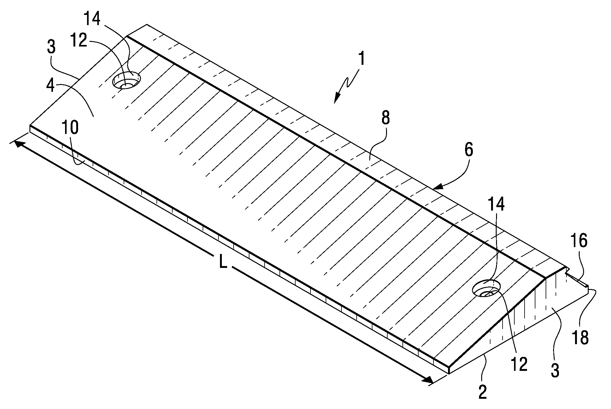
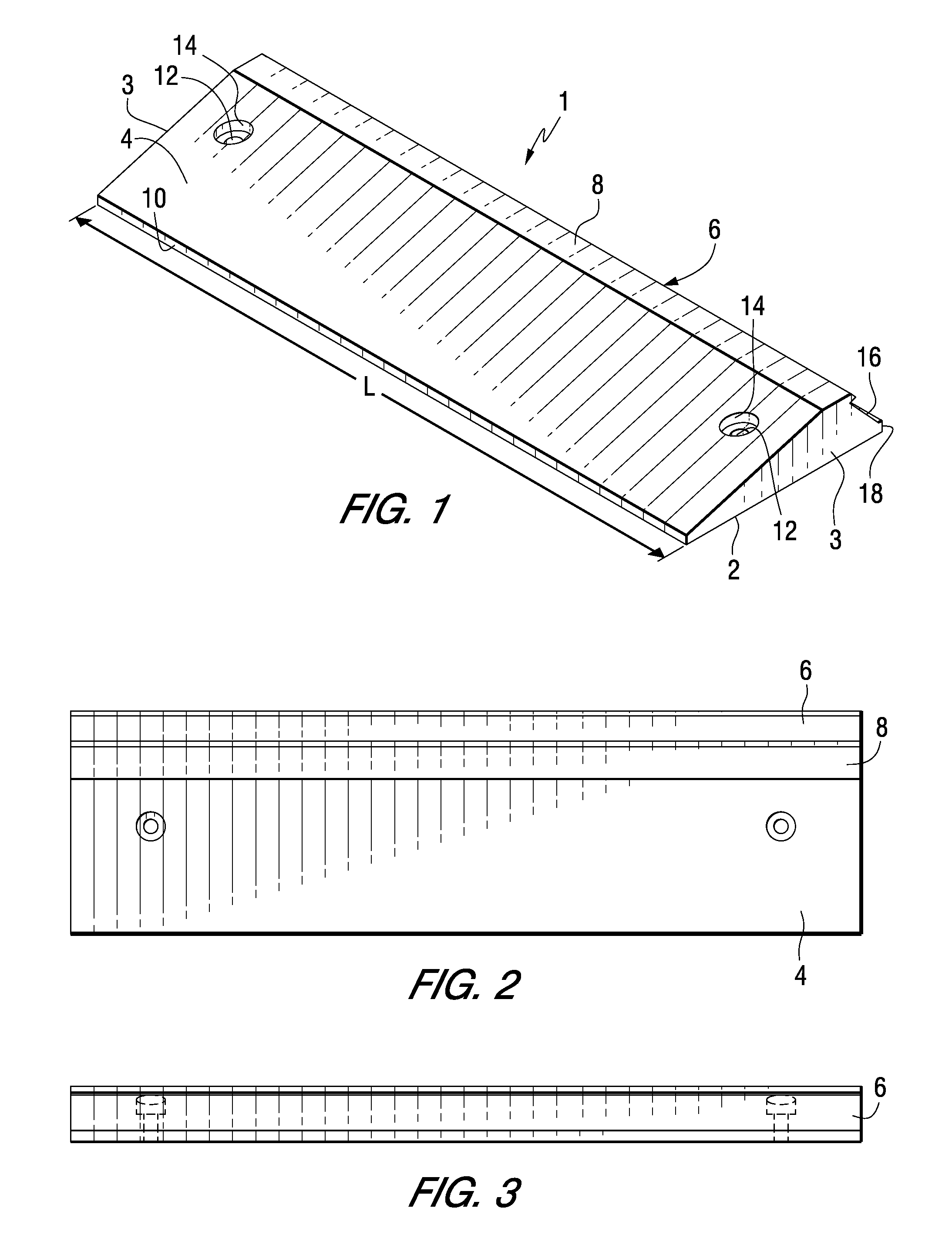
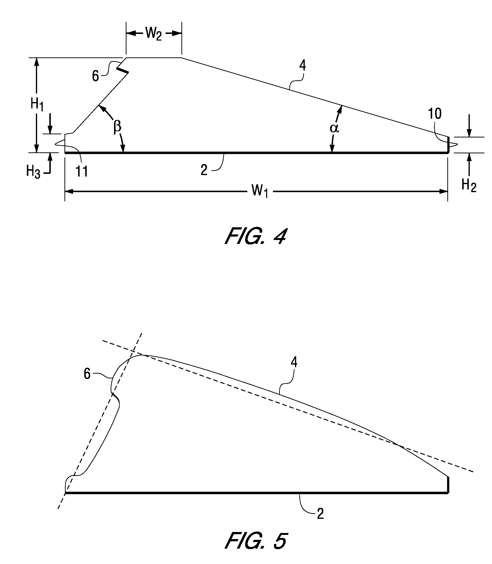
[0014]A one-way speed bump 1 according to one embodiment of the present invention shown in FIGS. 1-3. The speed bump 1 has a generally flat bottom surface 2, which faces the ground. In one embodiment, the ground may comprise pavement. The term “pavement” as used herein is not meant to be one of limitation and can be, for example, a roadway, highway, aisle way, row or parking lot. The speed bump 1 may be positioned to traverse all or a portion of a road. As used herein, “road” may be used interchangeably with aisle or any other surface upon which vehicles travel. The length of the speed bump, shown as L in FIG. 1, varies depending on the on the width of the road and may be of whatever length is necessary to control traffic. This may include aligning more that one speed bump 1 alongside others. It should be apparent that the length of the speed bump is not a limitation of the device. Rather, length is a function of the road or aisle to be controlled. In one embodiment, L is 36 inches....


PUM


Abstract

A one-way speed bump for controlling both direction and speed of traffic is described. The speed bump has a shallow front face and a steep rear face. Vehicles approaching the front face of the speed bump are allowed to pass over the speed bump at a controlled rate of speed. Vehicles attempting to pass from the wrong direction will engage the steep rear face of the speed bump. This will cause the vehicle to be jolted and possibly damaged. Indicia may be provided on the steep rear face to warn drivers that they are traveling in the wrong direction.

Description

CROSS REFERENCE TO RELATED APPLICATION[0001]This application claims the benefit of U.S. Provisional Patent Application Ser. No. 60 / 779,345 filed Mar. 3, 2006, which is herein incorporated by reference.FIELD OF THE INVENTION[0002]The present invention relates generally to speed bumps and more particularly to one-way speed bumps which control both the speed and direction of vehicular traffic.BACKGROUND INFORMATION[0003]In the interest of safety to other vehicles and pedestrians speed of motor vehicles should be kept to a safe level. One means for controlling vehicular speed is through the use of a speed bump placed across a road other path of travel for vehicles. Speed bumps are typically dimensioned so that a vehicle may pass over at a relatively slow speed without jarring the driver or causing damage to the vehicle.SUMMARY OF THE INVENTION[0004]The present invention provides a one-way speed bump for controlling both direction and speed of traffic. The speed bump has a shallow front ...

Claims


Application Information

Patent Timeline
Patent Type & Authority Applications(United States)
IPC IPC(8): E01F11/00E01F9/529
CPCE01F13/10E01F9/047E01F9/529
Inventor BROUGHTON, SCOTTHUFF, MATTHEW J.EVANS, R. DOUGLAS
Owner NEW PIG CORP
Why Eureka
Try Eureka