Image forming apparatus

Active Publication Date: 2007-11-15
FUJIFILM BUSINESS INNOVATION CORP
View PDF9 Cites 0 Cited by
  • Summary
  • Abstract
  • Description
  • Claims
  • Application Information

AI Technical Summary

Problems solved by technology

However, since the space on the back surface side of the conveyor belt stretched between the two tension rollers becomes extremely narrow when the conveyor belt mechanism is compact, as described above, the bent front e

Method used


Image

  • Image forming apparatus
  • Image forming apparatus
  • Image forming apparatus

Examples


Example

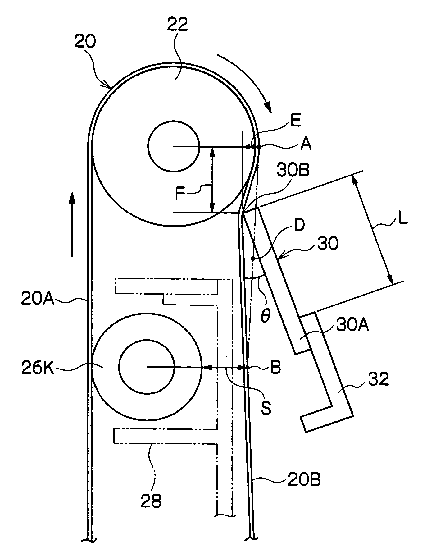
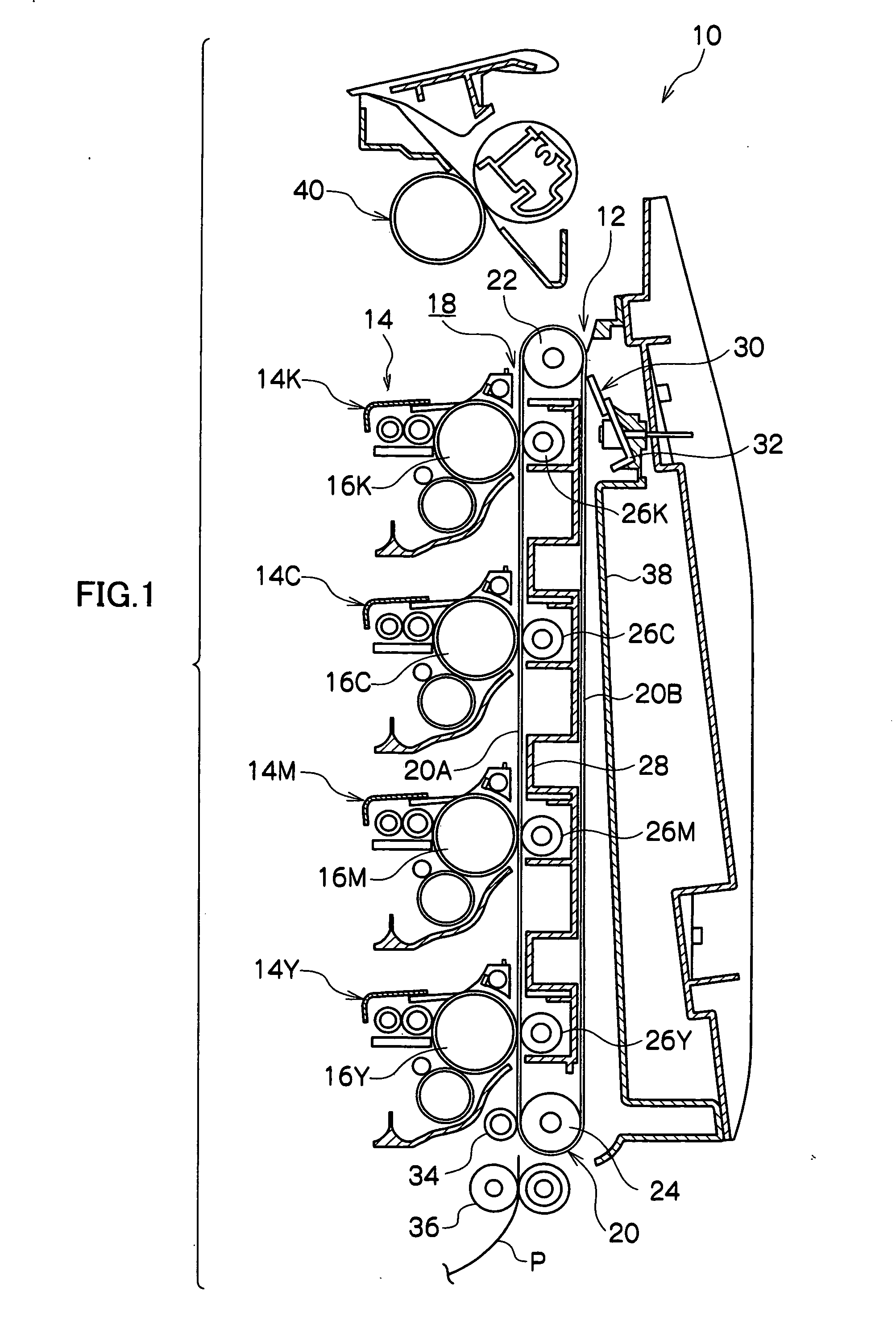
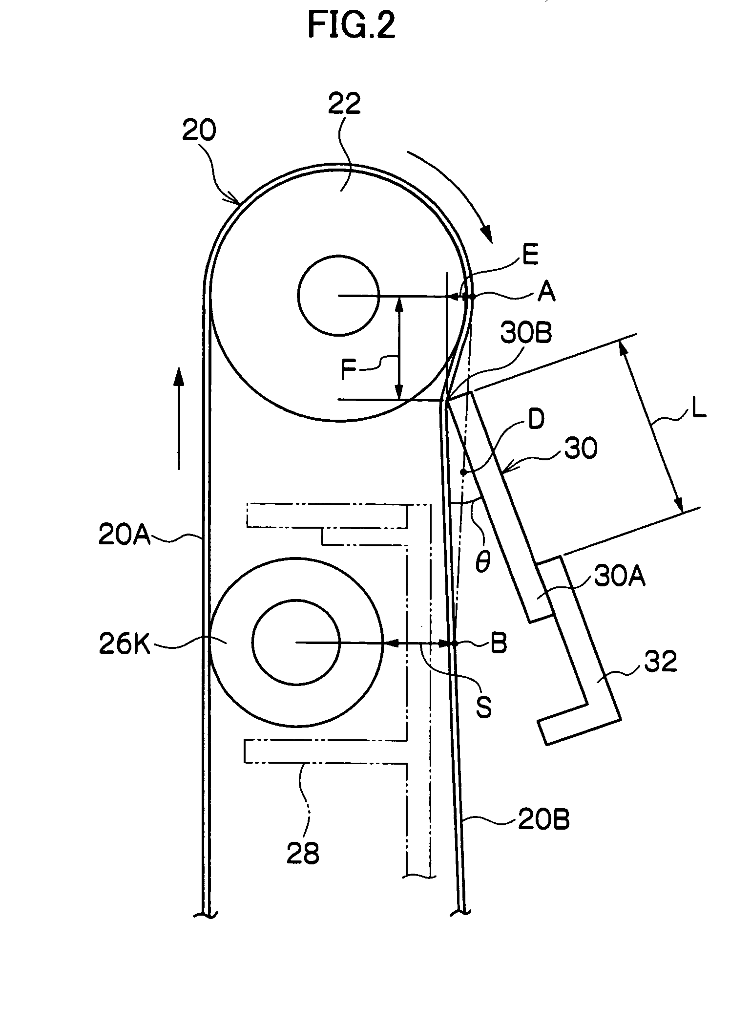
[0011]The exemplary embodiment of the present invention will now be described in detail based on examples shown in the figure. FIG. 1 is a schematic side view showing a configuration near a transfer unit 12 of an image forming apparatus 10 according to an exemplary embodiment of the invention, and FIGS. 2 and 3 are schematic side views showing a cleaning blade 30. As shown in FIG. 1, an image forming unit 14 including a photosensitive drum 16 is arranged for each color along a paper conveying direction with respect to the transfer unit 12 including a conveyor belt 20 that configures a paper conveying path 18.

[0012]The photosensitive drums 16Y to 16K are arranged at a predetermined interval in a state projected to a predetermined height to the paper conveying path 18 side (conveyor belt 20 side) in each image forming unit 14Y to 14K of yellow (Y), magenta (M), cyan (C), black (K) from the upstream side of the paper conveying direction, which is the lower side in FIG. 1. A fixing devi...


PUM


Abstract

The image forming apparatus includes two tension rollers; a conveyor belt movably supported at the two tension rollers; a plurality of transfer parts that are arranged on the back surface side of the conveyor belt and between the two tension rollers, that contact one surface of the back surface of the conveyor belt, and that form a predetermined clearance with an opposite portion of the back surface of the conveyor belt; and a cleaning blade for removing residual toner remaining on the conveyor belt. The cleaning blade has the front end contacting the conveyor belt at a predetermined pressure. The cleaning blade is arranged at a position where the back surface of the conveyor belt distorted by the front end does not contact the tension roller.

Description

BACKGROUND OF THE INVENTION[0001]1. Technical Field[0002]The present invention relates to image forming apparatuses, more specifically, to a cleaning mechanism of a conveyor belt for conveying a recording medium.[0003]2. Related Art[0004]In the cleaning mechanism, the conveyor belt is often stretched simply between two tension rollers (driving roller and driven roller) having a small diameter, for example, in order to miniaturize the conveyor belt mechanism in an image forming apparatus for transferring a toner image of yellow, magenta, cyan, black on a recording paper (recording medium) and forming an image. A configuration of contacting the front end of a cleaning blade made of rubber at a predetermined pressure is adopted when cleaning the surface of the conveyor belt. The cleaning blade is arranged at a predetermined angle to a non-conveying surface, which is a surface of the conveyor belt that is not the paper conveying surface.[0005]However, the cleaning blade configured as ab...

Claims


Application Information

Patent Timeline
IPC IPC(8): G03G21/00B65G45/00
CPCB65G45/12G03G2215/1614G03G15/168
Inventor SUGANUMA, TOSHIHIRO
Owner FUJIFILM BUSINESS INNOVATION CORP
Why Eureka
Try Eureka