Automobile body structure

A technology of automobile body and side frame, which is applied in the direction of upper structure, lower structure, upper structure sub-assembly, etc. It can solve the problems of reducing the collision energy absorption performance and making it difficult to ensure the crushing stroke, so as to improve the energy absorption performance and compressive strength. The effect of stroke improvement

Active Publication Date: 2018-10-23
HONDA MOTOR CHINA INVESTMENT CO LTD
View PDF8 Cites 0 Cited by
  • Summary
  • Abstract
  • Description
  • Claims
  • Application Information

AI Technical Summary

Problems solved by technology

[0003] In addition, in the prior art described above, when the front-rear middle part of the lower load transmission member is bent downward under the impact load of a frontal collision, the lower end of the bent lower load transmission member comes into contact with the road surface and is pushed up. , the front end of the front subframe will be raised, and when the engine and transmission located in front of the front subframe receive a collision load and move backward, they will interfere with the front end of the front subframe, making it difficult to secure a crush stroke. , may reduce the energy absorption performance in the event of a collision

Method used


Image

  • Automobile body structure
  • Automobile body structure
  • Automobile body structure

Examples


Embodiment Construction

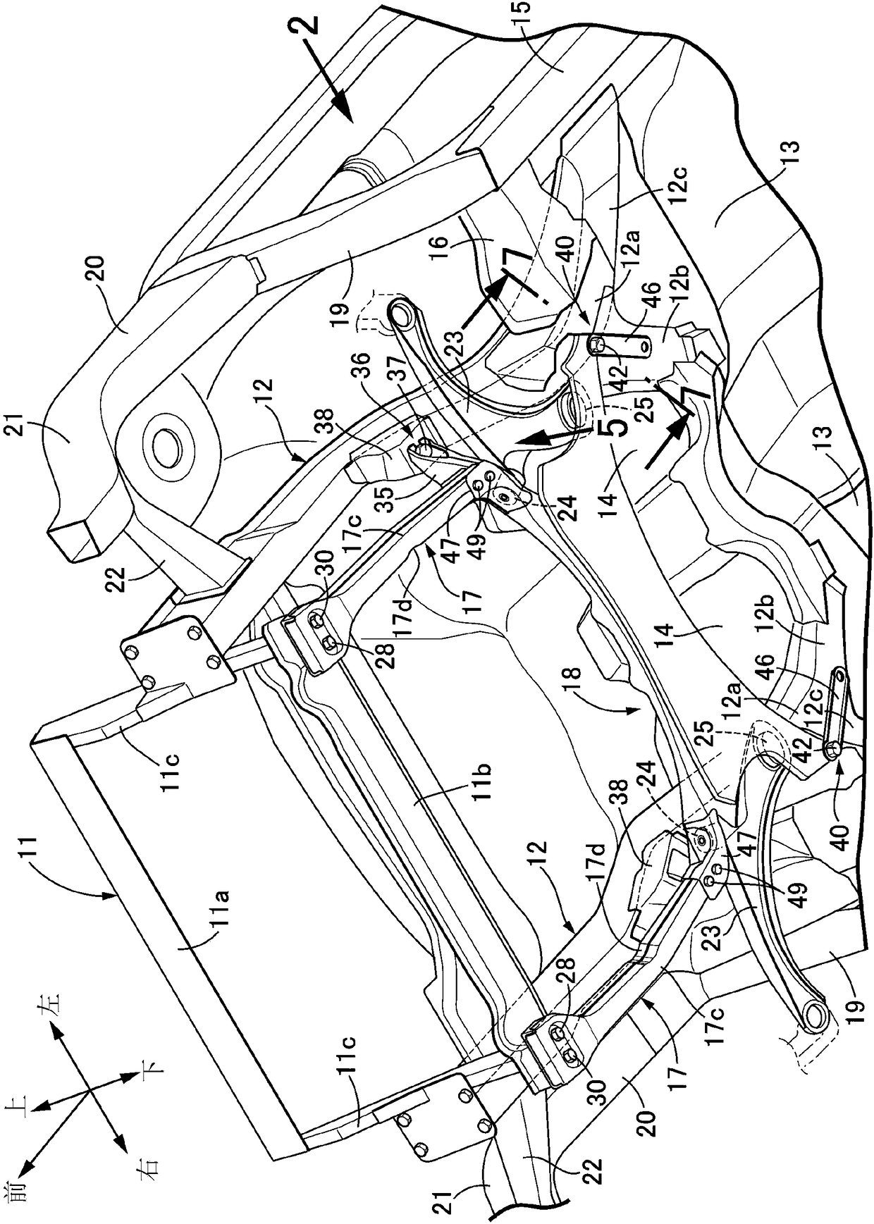
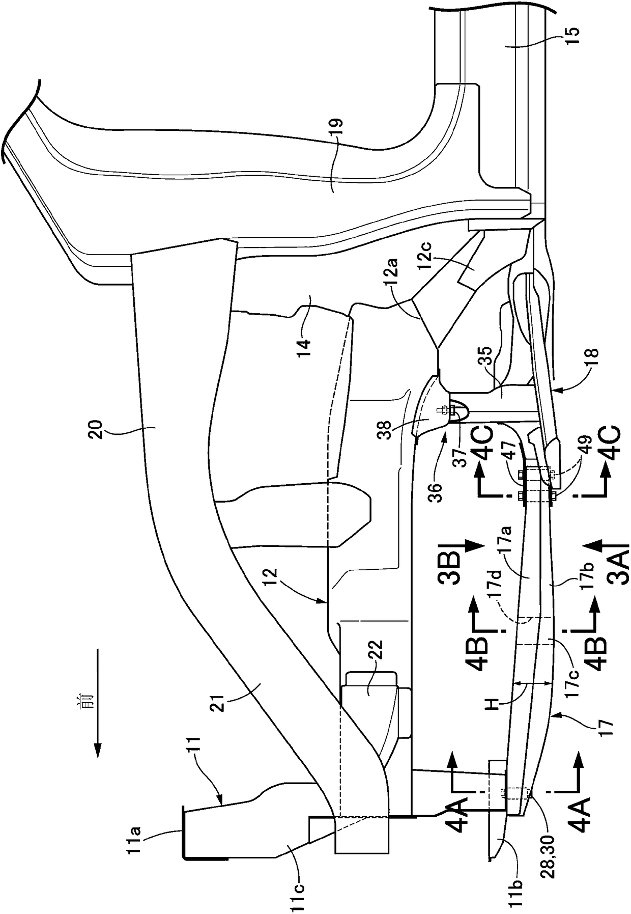
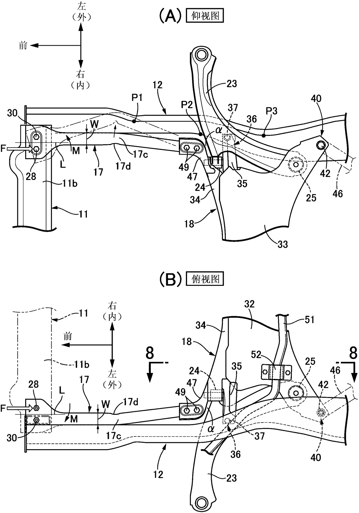
[0033] Below, according to Figure 1 to Figure 9 , the embodiment of the present invention will be described. In addition, the front-rear direction, the left-right direction (vehicle width direction), and the up-down direction in this specification are defined based on the occupant sitting in the driver's seat.

[0034] Such as figure 1 and figure 2 As shown, a front bulkhead 11 is arranged at the front end of the automobile body. The front bulkhead 11 is combined into a rectangular frame by an upper side 11a and a lower side 11b extending in the vehicle width direction, and a pair of left and right sides 11c, 11c extending in the vertical direction. shape formed. The rear branches of the pair of left and right front side frames 12, 12 extending in the front-rear direction are divided into two branches. The branched portions 12 a, 12 a of the front side frames 12 , 12 are connected to the front surface of a dash lower member 14 standing forward and upward from the front end...


PUM


Abstract

The invention provides an automobile body structure. Lower load transmission components (17) have a roughly-certain automobile width direction width (W) in the overlooking observation process, bent parts (17c) formed on the middle portions in the front-back direction are bent in the mode of protruding outwards in the automobile width direction, groove parts (17d) extending in the up-down directionare formed in the inner walls of the bent parts (17c) in the automobile width direction, when the lower load transmission components (17) are observed from the side faces, the upper walls are even, the lower walls are bent in the mode of protruding downwards, and the positions near the bent parts (17c) hereby have the largest up-down direction height (H). Therefore, when a head-on collision happens to an automobile, the lower load transmission components (17) are bent to the outer sides in the automobile width direction, the situation that the lower load transmission components (17) make contact with the road surface and a front auxiliary automobile frame (18) is pushed up is avoided, and the crushing travel of retraction of an engine and a transmission hereby can be guaranteed.

Description

technical field [0001] The present invention relates to an automobile body structure that connects the lower side of a front bulkhead and a front subframe through a pair of left and right under load path members, wherein the A pair of left and right lower load transmission members have a closed cross section and extend in the front-rear direction. Background technique [0002] According to Japanese Patent Laid-Open Publication No. 2012-153263, it is known that a pair of left and right lower load transmission members (lower interference rod members 137) are used to connect the lower side of the rectangular frame-shaped front bulkhead and the front panel disposed behind the front bulkhead. The front end of the subframe, wherein the pair of left and right lower load transmission members are hollow rod-shaped members bent downward and having a predetermined cross section, and the lower load transmission member The front-to-back direction middle part is bent downward to absorb t...

Claims


Application Information

Patent Timeline
IPC IPC(8): B62D21/15B62D25/08
CPCB62D21/152B62D25/08B62D25/088
Inventor 安在博之白幡卓也佐藤宪田米浩司缪杰锋
Owner HONDA MOTOR CHINA INVESTMENT CO LTD
Why Eureka
Try Eureka