Telescopic steering apparatus

a technology of telescopic steering and steering column, which is applied in the direction of steering column, steering wheel, steering components, etc., can solve the problems of increasing processing cost, increasing processing cost, and requiring a large amount of time to perform the processing, so as to reduce processing cost and reduce processing cost. , the effect of low cos

Active Publication Date: 2015-06-04
NSK LTD
View PDF12 Cites 3 Cited by
  • Summary
  • Abstract
  • Description
  • Claims
  • Application Information

AI Technical Summary

Benefits of technology

[0026]According to the one aspect of the invention, it is possible to provide the telescopic steering apparatus having the structure capable of stably maintaining the inner column radially inside the outer column and absorbing a shock load upon a secondary collision at low cost. First, the reason why the structure capable of stably maintaining the inner column radially inside the outer column can be implemented at low cost is because the outer column, including the supporting portion for supporting the inner column, and the movable bracket are integrally formed by an expansion forming such as a hydroforming for example. That is, even when the supporting portion has multiple (e.g., three or more) protuberances, it is possible to reduce the processing cost and to obtain the supporting portion having the high stiffness.
[0027]The reason why the structure capable of absorbing the shock load upon secondary collision cam be implemented at low cost is because the inner peripheral surface of the outer column is provided with the shock absorbing portion, the diameter of the inscribed circle of which is smaller than the outer diameter of the inner column, at the location shifted toward one side in the axial direction from the axial end face of the inner column, and the shock absorbing portion is formed by the expansion forming such as the hydroforming for example. That is, upon secondary collision, the inner column and the outer column are relatively displaced in a compressing direction such that the axial end face of the inner column frictionally moves along the shock absorbing portion of the outer column. The shock absorbing portion functions as a resistance against the compression of the inner column and the outer column and thus absorbs the shock energy applied to the steering wheel upon the secondary collision, thereby alleviating the shock applied to the driver body colliding with the steering wheel. Since the shock absorbing portion is directly formed at the outer column by the expansion forming, it is not necessary to provide a separate shock absorption member. As a result, it is possible to reduce the processing cost, the component management cost and the assembling cost.
[0028]When the supporting portion provided on the inner peripheral surface of the outer column and the outer peripheral surface of the inner column overlapping the supporting portion are configured to contact each other at only three locations along the circumferential direction, it is possible to enable the supporting portion to reliably contact the outer peripheral surface of the inner column. Also, since the number of the contacting locations is just three, it is possible to easily perform the process for making the contacting conditions the same for all the contacting locations.
[0029]When the supporting portion of the outer column is finished by cutting or pressing, it is possible to more stabilize the contacting condition of the supporting portion and the outer peripheral surface of the inner column. When the supporting portion has multiple protuberances, it is possible to reduce the processing cost and to stably support the inner column by the supporting portion, compared to a configuration where the cutting work is performed for an entire circumference of an inner peripheral surface of an outer column having a simple cylindrical shape.
[0030]When the shock absorbing portion has the protuberances that protrude radially inwards from the inner peripheral surface of the outer column at a plurality of locations along a circumferential direction on the inner peripheral surface of the outer column, it is possible to prevent the inner column from being inclined relative to the outer column, based on the load of the complex directions applied to the inner column and the outer column upon the compression of the inner column and the outer column, and to secure the stable energy absorption performance. Furthermore, it is possible to adjust the energy absorption performance by adjusting the number of the protuberances.
[0031]When the supporting portion and the shock absorbing portion are aligned in phase with respect to the circumferential direction, it is possible to easily configure that the supporting portion and the shock absorbing portion are continuous in the axial direction. When the supporting portion and the shock absorbing portion are made to be continuous in the axial direction, the inner column and the outer column can be smoothly (continuously) and stably compressed upon the secondary collision. As a result, it is possible to stably absorb the shock load upon secondary collision.

Problems solved by technology

For the steering apparatus, the cutting work for finishing an inner diameter of the outer column 12 with accuracy is troublesome and the processing cost is thus increased.
Thus, when the inner diameter precision of the outer column 12 is not sufficient, a partial contact is caused, so that the inner column 11 cannot be stably maintained.
Hence, it takes much time to perform the processing and the processing cost is thus increased.
However, when the multiple protuberances 34, 34 are provided, like the outer column 12a, the process for making the contacting conditions be the same is troublesome.
Hence, it is difficult to secure the stiffness for stably supporting the inner column 11b radially inside the outer column 12b.
Also, the operation of welding the other end of the clamped portions 23a, 23a to the outer column 12b consumes much time, which increases the processing cost.
According to the structure of the related art, since the separate energy absorption member is provided, the component manufacturing, the component management and the assembling operation are troublesome, which increases the cost.

Method used


Image

  • Telescopic steering apparatus
  • Telescopic steering apparatus
  • Telescopic steering apparatus

Examples


first embodiment

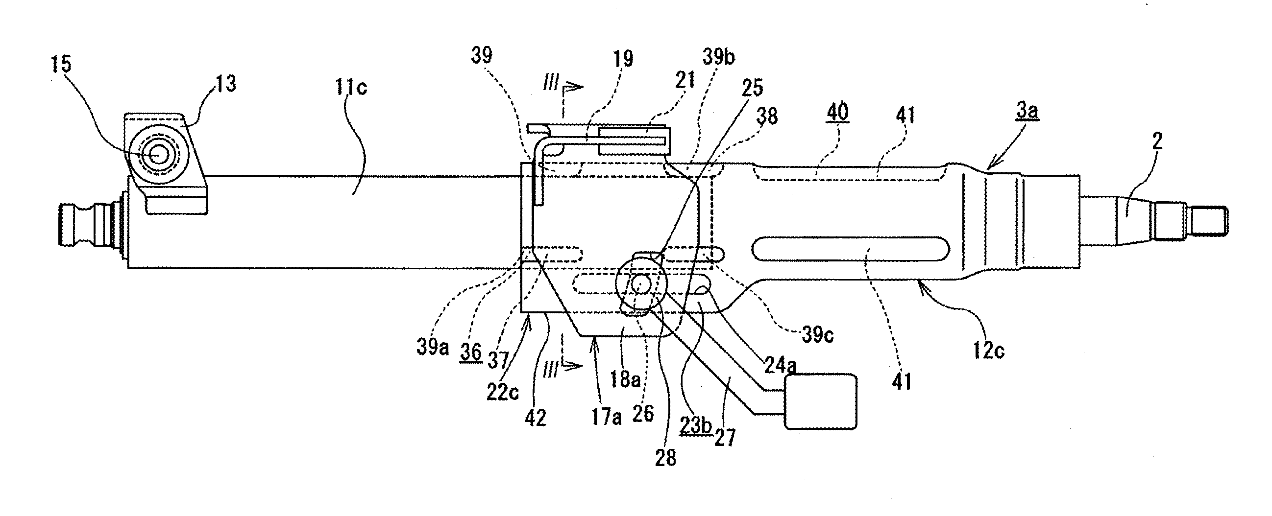
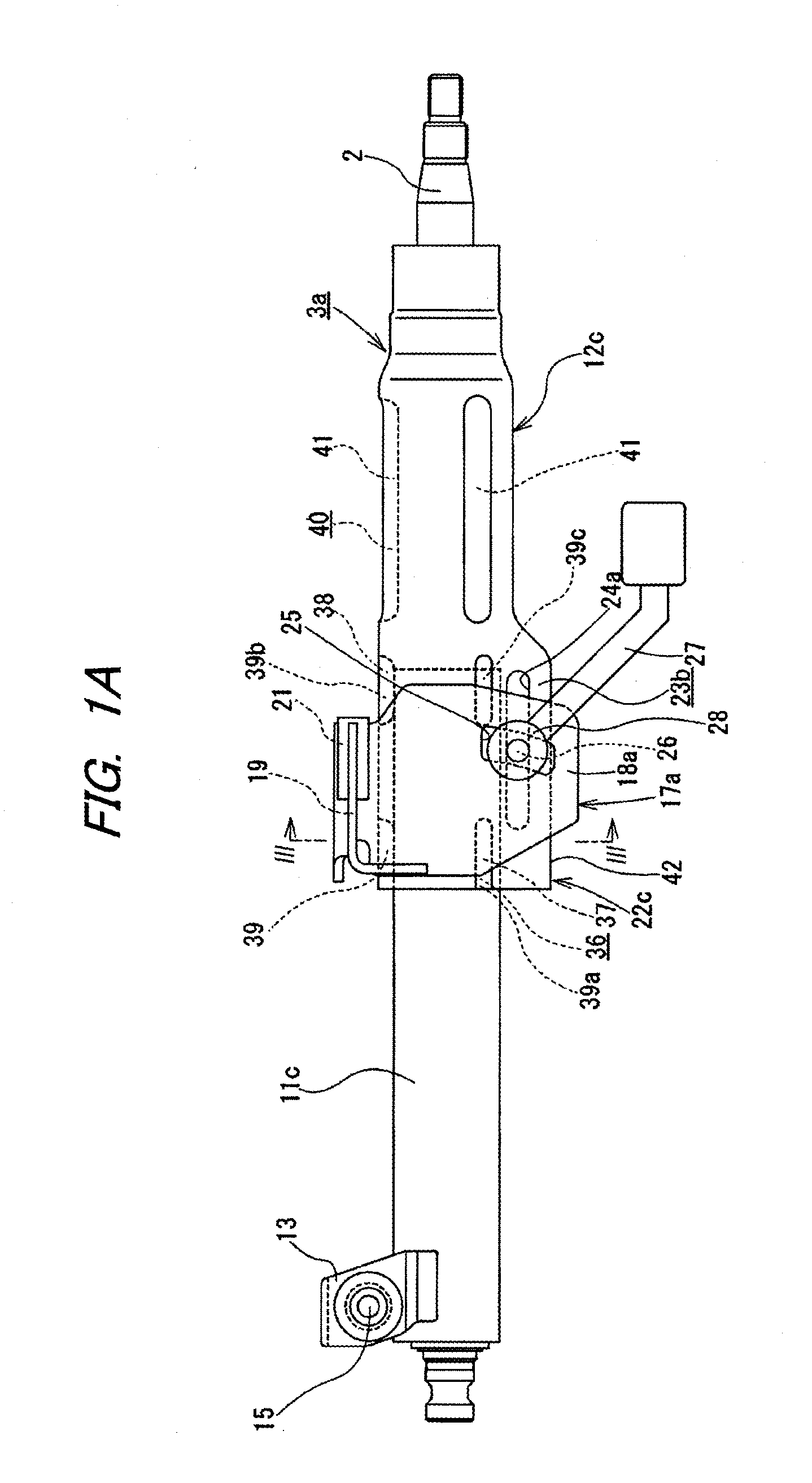
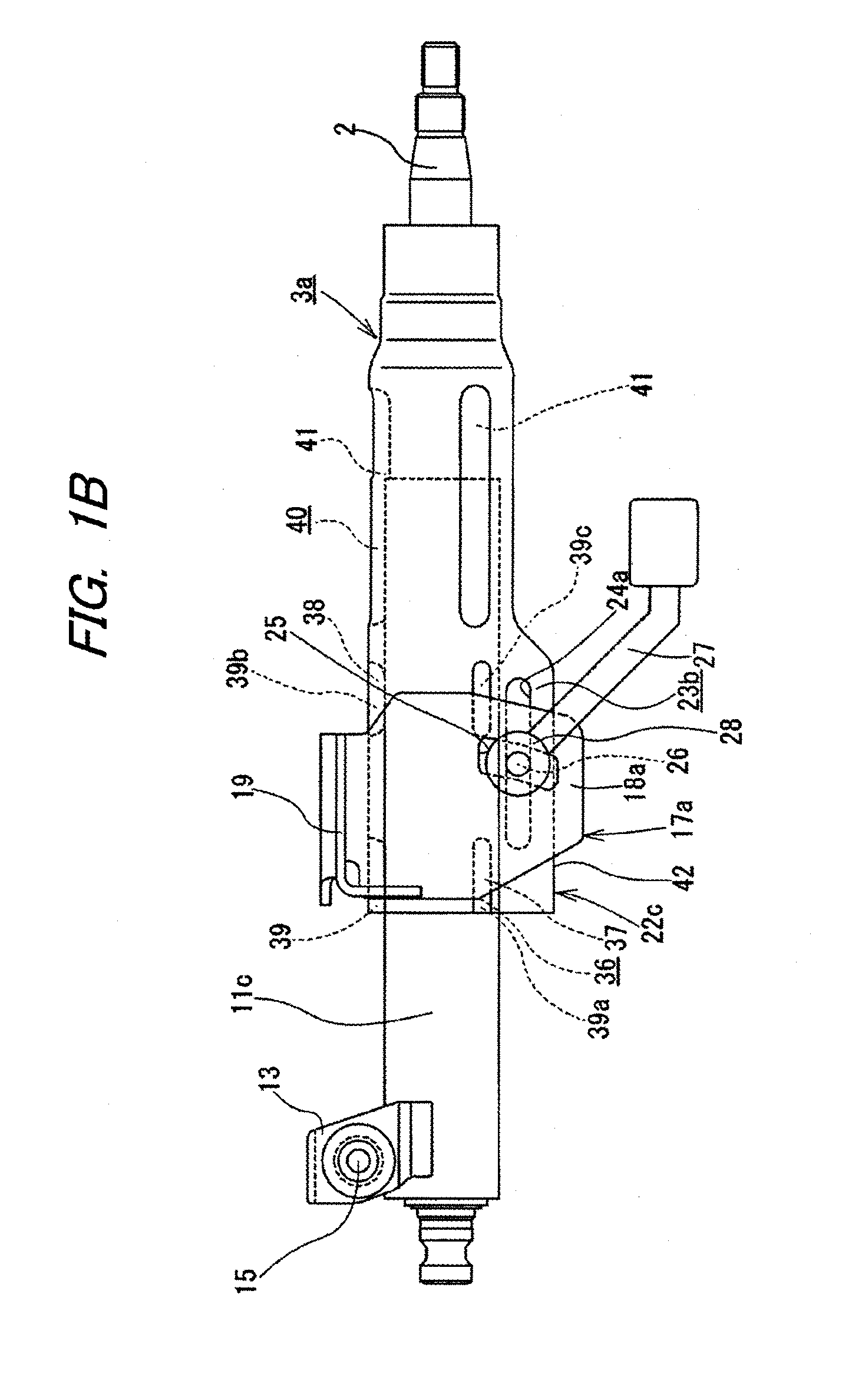
[0048]FIGS. 1 to 5 show a telescopic steering apparatus according to the invention. The telescopic steering apparatus has a telescopic mechanism configured to adjust a front-rear position of a steering wheel 1 (see FIG. 11) and a tilt mechanism configured to adjust an upper-lower position of the steering wheel 1, like the structure shown in FIGS. 11 and 12. However, the invention is also applicable to a structure having no tilt mechanism. A method of operating the telescopic steering apparatus is similar to that of the telescopic steering apparatus of the related art shown in FIGS. 11 and 12. The illustrations and descriptions of parts similar to those of the related art are omitted or simplified.

[0049]A steering column 3a of the telescopic steering apparatus of this embodiment has an outer column 12c configured as an upper column of the steering wheel 1-side (see FIG. 11) and an inner column 11c configured as a lower column of a side distant from the steering wheel 1.

[0050]A front ...

third embodiment

[0065]FIG. 7 shows an outer column 12e of a telescopic steering apparatus according to the invention. The respective protuberances 39, 39a, 39b, 39c of the supporting portion 36 (the front and rear supporting portions 37, 38) of the outer column 12e are provided in a similar manner as in the above embodiment (see FIGS. 1 to 4). Respective protuberances 41a, 41a of a shock absorbing portion 40a are provided at locations (the upper and lower locations are opposite to the above embodiment) that are symmetric to the supporting portion 36 (the front and rear supporting portions 37, 38) with respect to a virtual plane a passing through a central axis O36 of an inscribed circle X36 (see FIG. 4) of the supporting portion 36 and perpendicular to the side wall portions 18a, 18a of the fixed bracket 17a.

[0066]According to the telescopic steering apparatus, it is possible to increase the contacting locations along the circumferential direction (in the present example, six locations) between th...


PUM

PropertyMeasurementUnit
angleaaaaaaaaaa
inner diameteraaaaaaaaaa
widthaaaaaaaaaa

Abstract

A telescopic steering apparatus includes a steering column having an outer column and an inner column. An inner peripheral surface of the outer column has a supporting portion that supports the inner column. An inner peripheral surface of the outer column further has a shock absorbing portion at a location shifted toward one side in an axial direction from an axial end face of the inner column, a diameter of an inscribed circle of the shock absorbing portion being smaller than an outer diameter of the inner column. The outer column, including the supporting portion and the shock absorbing portion, and a movable bracket are integrally formed by an expansion forming.

Description

TECHNICAL FIELD[0001]The invention relates to a telescopic steering apparatus configured to adjust a front-rear position of a steering wheel.BACKGROUND ART[0002]FIGS. 11 and 12 illustrate a tilt-telescopic steering apparatus disclosed in Patent Document 1. The steering apparatus has a steering shaft 2 having a rear end portion to which a steering wheel 1 is fixed, a steering column 3 rotatably supporting the steering shaft 2 therein, a steering force assist device 5 which applies assist torque to the steering shaft 2 using an electric motor 4 as an auxiliary power source, and a steering gear unit 7 which pushes or pulls tie-rods 6, 6 in accordance with a rotation of the steering shaft 2. In this description, a front-rear direction means a front-rear direction of a vehicle.[0003]The steering shaft 2 has an inner shaft 8 and an outer shaft 9. The inner shaft 8 and the outer shaft 9 are combined to transmit a rotational force and to be relatively displaced in an axial direction. A fron...

Claims


Application Information

Patent Timeline
Patent Type & Authority Applications(United States)
IPC IPC(8): B62D1/19B62D1/184B21D26/033B62D1/185
CPCB62D1/192B21D26/033B62D1/184B62D1/185B21D53/88B62D1/16
Inventor MORIYAMA, SEIICHI
Owner NSK LTD
Why Eureka
Try Eureka