Vehicle rear portion structure

a rear portion and vehicle technology, applied in the field of vehicle rear portion structure, can solve the problems of becoming difficult to achieve a standardization of the rear side members in plural types of vehicles, and becoming difficult for the rear end portion of the rear side member to bend in the vehicle up-down direction

Active Publication Date: 2017-05-23
TOYOTA JIDOSHA KK
View PDF19 Cites 0 Cited by
  • Summary
  • Abstract
  • Description
  • Claims
  • Application Information

AI Technical Summary

Benefits of technology

[0019]According to the vehicle rear portion structure pertaining to the third aspect, the corner portions where the lower wall portion and the sloping wall portions of the shock absorbing member meet are placed on the vehicle front-rear direction rear side of the lower end portion of the load transmitting projecting portion. Because of this, in a case where a load has been input from the vehicle front-rear direction rear side to the shock absorbing member in accompaniment with a rear impact, the load is transmitted to the lower end portion of the load transmitting projecting portion via the corner portions where the rigidity is higher compared to other regions of the lower wall portion. As a result, the transmission efficiency of the load transmitted from the lower wall portion of the shock absorbing member to the load transmitting projecting portion is improved. Consequently, the rear end portion of the rear side member can be more reliably allowed to bend at the time of a rear impact.
[0026]Furthermore, the mode of deformation (deformed shape) of the rear side member is stable because the rear side member becomes bent in the vehicle up-down direction at the front end side of the shock absorbing member bracket and the rear end side of the cross member bracket in accompaniment with the rear impact. Consequently, at the time of a rear impact the impact energy can be efficiently absorbed in the rear side member.
[0030]Furthermore, the mode of deformation (deformed shape) of the rear side member is more stable because the rear side member becomes bent in the vehicle up-down direction at the front end side of the shock absorbing member bracket, the rear end side of the cross member bracket, and the one end side of the suspension bracket in accompaniment with the rear impact. Consequently, at the time of a rear impact the impact energy can be more efficiently absorbed in the rear side member.
[0032]According to the vehicle rear portion structure pertaining to the seventh aspect, the load transmitting projecting portion includes the triangular-shaped load transmitting bead portion spanning the distance between the reinforcement portion and the load receiving portion as seen from the outer side in the vehicle width direction. Because of this, for example, when a load is input from the shock absorbing member to the load transmitting bead portion in accompaniment with a rear impact, the load is transmitted via the load transmitting bead portion and the reinforcement portion upward in the vehicle up-down direction and forward in the vehicle front-rear direction to the rear end portion of the rear side member. As a result, the rear end portion of the rear side member becomes bent in such a way as to point upward in the vehicle up-down direction starting at the front end side of the reinforcement portion where the bending rigidity suddenly changes. Consequently, at the time of a rear impact the impact energy can be efficiently absorbed in the rear side member.

Problems solved by technology

For that reason, there is the potential for it to become difficult to achieve a standardization of the rear side members in plural types of vehicles in which the rear impact performance required of the rear side members is different as described above.
For that reason, it becomes difficult for the rear end portion of the rear side member to bend in the vehicle up-down direction starting at the front end side of the reinforcement portion.

Method used


Image

  • Vehicle rear portion structure
  • Vehicle rear portion structure
  • Vehicle rear portion structure

Examples


Embodiment Construction

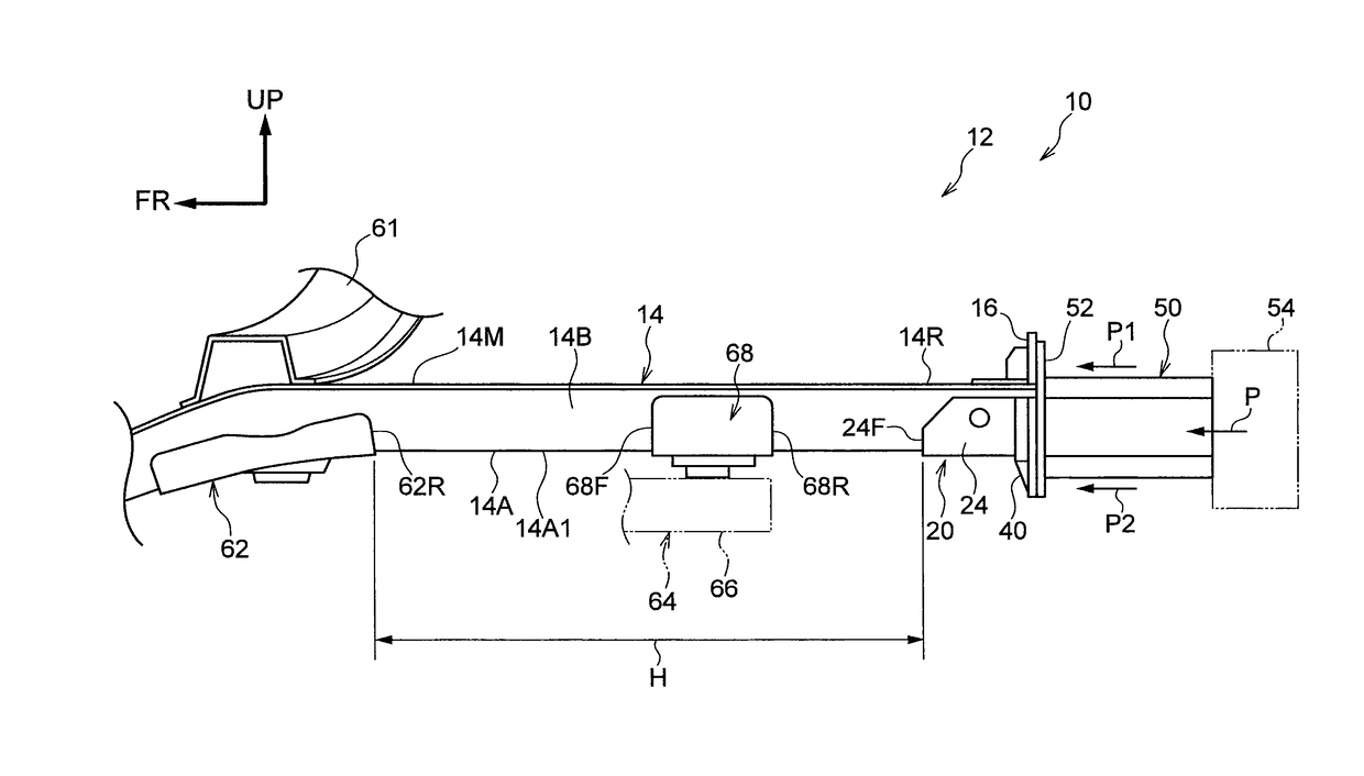
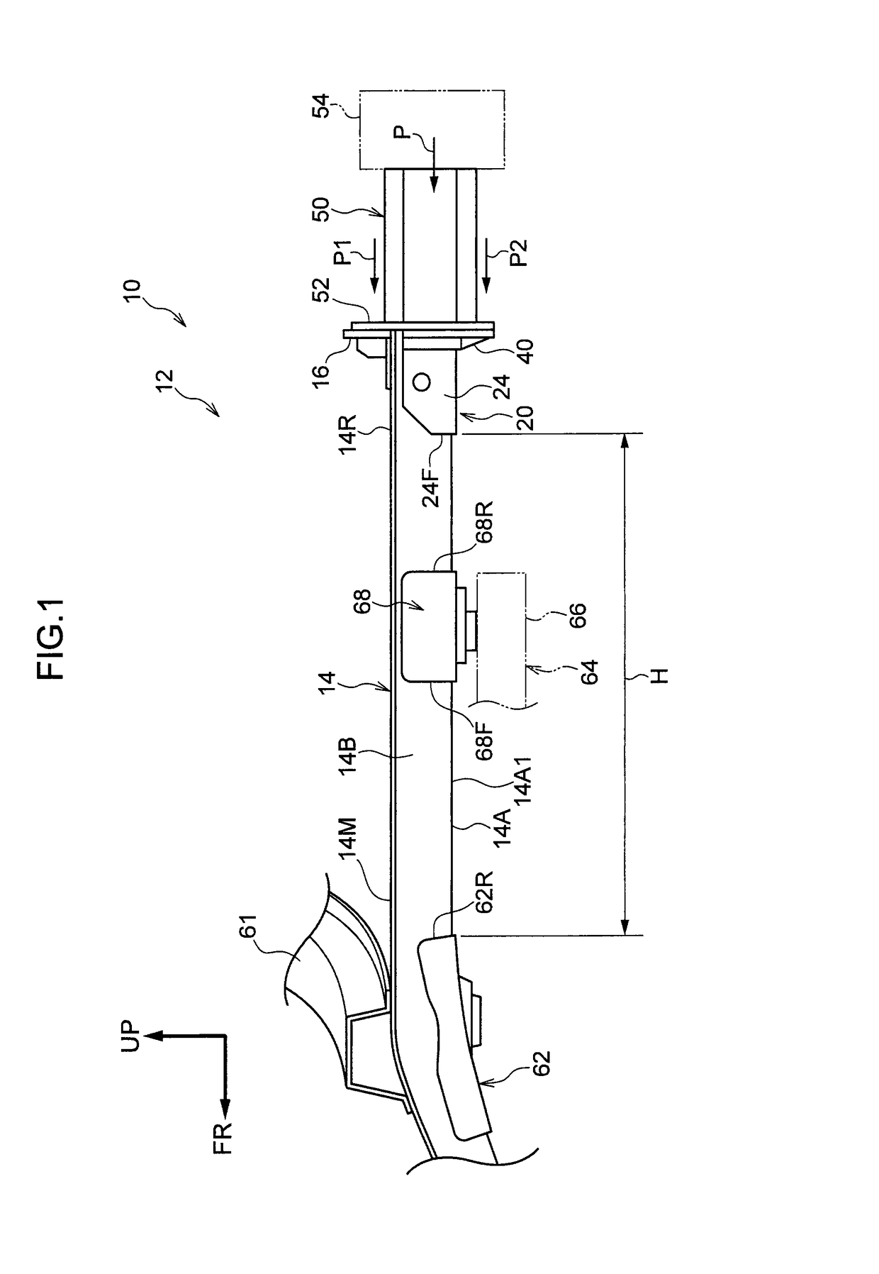
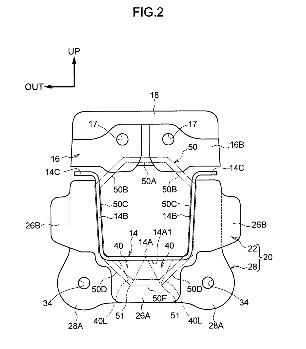
[0044]A vehicle rear portion structure pertaining to an embodiment of the present invention will be described below. It should be noted that arrow FR appropriately shown in the drawings indicates a forward direction in the vehicle front-rear direction. Furthermore, arrow UP indicates an upward direction in the vehicle up-down direction. Moreover, arrow OUT indicates an outward direction (a vehicle body left side) in the vehicle width direction. Furthermore, unless otherwise noted, front and rear and up and down in the following description will be understood to mean front and rear in the vehicle front-rear direction and up and down in the vehicle up-down direction.

[0045](Vehicle Rear Portion Structure)

[0046]FIG. 1 shows a vehicle rear portion 12 to which a vehicle rear portion structure 10 pertaining to the present embodiment has been applied. The vehicle rear portion structure 10 is equipped with a pair of rear side members 14, an upper bracket 16, a lower bracket 20, a shock absor...


PUM


Abstract

A vehicle rear portion structure includes: a rear side member front-rear direction; a shock absorbing member that is placed at the rear side of the rear side member; and a lower bracket that has a reinforcement portion that is joined to a rear end portion of the rear side member, a load receiving portion that extends downward from a rear end portion of the reinforcement portion and to which the shock absorbing member is joined, and a load transmitting bead portion that is disposed spanning the distance between the load receiving portion and a lower wall portion of the reinforcement portion, with a length L to which the load transmitting bead portion projects in the vehicle front-rear direction becoming longer heading from the load receiving portion to the reinforcement portion.

Description

CROSS-REFERENCE TO RELATED APPLICATION[0001]This application is based on and claims priority under 35 USC 119 from Japanese Patent Application No. 2014-263016 filed on Dec. 25, 2014, the disclosure of which is incorporated by reference herein.TECHNICAL FIELD[0002]The present invention relates to a vehicle rear portion structure.RELATED ART[0003]Vehicle rear portion structures where rear side members placed along the vehicle front-rear direction are disposed in the side portions of the vehicle rear portion are known (e.g., see Japanese Patent Application Laid-open (JP-A) No. 2014-008835, JP-A No. 2009-262660, JP-A No. 2014-125000, JP-A No. H08-175421, and JP-A No. 2006-069279).[0004]Among this type of vehicle rear portion structure, there is a vehicle rear portion structure which, by allowing the rear side members to bend in the vehicle up-down direction in accompaniment with an impact from an impactor on the vehicle rear surface (hereinafter simply called a “rear impact”), absorb th...

Claims


Application Information

Patent Timeline
Patent Type & Authority Patents(United States)
IPC IPC(8): B62D25/08B62D21/15
CPCB62D21/152B62D25/087
Inventor SUZUKI, HIROTOTAKAHASHI, HIDEYUKILI, WENFENG
Owner TOYOTA JIDOSHA KK
Why Eureka
Try Eureka