Tilting system for a flanging device

A technology of flanging and flanging, applied in the field of operation of workpieces, can solve problems such as complex and expensive structures, and achieve the effect of improving flanging, low cost and low cost

Inactive Publication Date: 2009-05-06
GM GLOBAL TECH OPERATIONS LLC
View PDF7 Cites 0 Cited by
  • Summary
  • Abstract
  • Description
  • Claims
  • Application Information

AI Technical Summary

Problems solved by technology

[0012] The disadvantage of these machines is that they are expensive and complex
Furthermore, for best results, hemming should only be performed after the different parts of the machine have been precisely adjusted

Method used


Image

  • Tilting system for a flanging device
  • Tilting system for a flanging device
  • Tilting system for a flanging device

Examples


Embodiment Construction

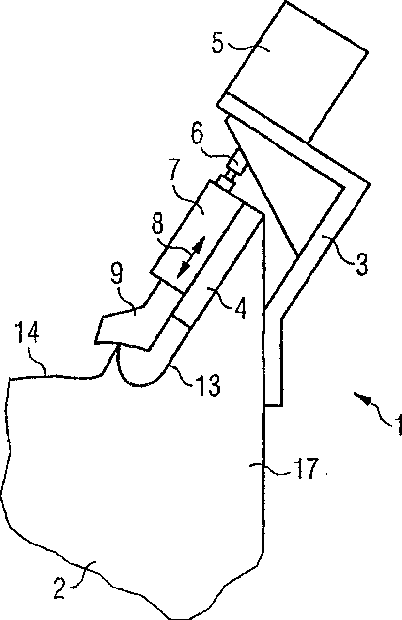
[0034] figure 1 A side view of the bending device 1 according to the invention is shown. The flanging device 1 is divided into a crimping machine base 2 with a cast-on slider 7 bracket 17, a welded structure 3 for mounting a pneumatic cylinder 5, a molded part 9, a guide device 4 and a piston rod 6 with an adjustment device .

[0035] A thin steel panel 14 rests on the crimping stand 2 . The welded structure 3 is meant to be the carrier of the pneumatic cylinder 5 and fastened to a bracket 17 designed as a cast part.

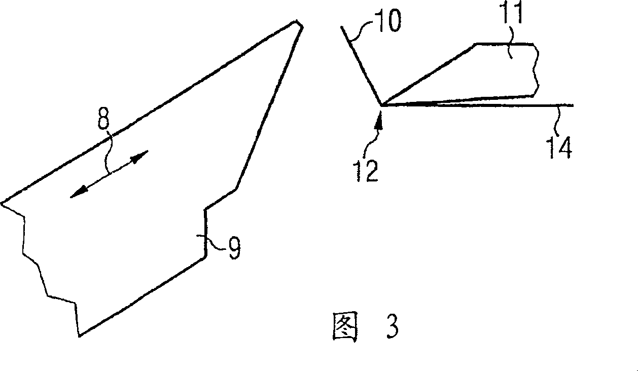
[0036] The machined upper side 13 of the bracket 17 serves here as a support for the guide 4 of the slide 7 which is connected to the piston rod 6 of the pneumatic cylinder 5 . A forming pincer 9 is provided on the front side of the slider 7 .

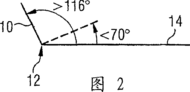
[0037] 2 and 3 show the deformation of the beading flange 10 of the thin steel panel 14 .

[0038] It can be seen from FIG. 2 that the beading flange 10 of the thin steel panel 14 is bent at a bending angle larger t...


PUM


Abstract

The invention relates to a flanging unit (1) with an actuator (5) having a slider (7) capable of reciprocating movement in a direction of movement (8), wherein the slider (7) A crimping forming pliers (9) is installed on the front side, which is used to deform the crimping flange (10) of the metal panel (14).

Description

technical field [0001] The present invention relates to the handling of workpieces when performing machining processes on workpieces, especially crimping. Background technique [0002] Hemming, also known as hemming and seaming, belongs to the chipless forming technology in the field of technology. This is understood to mean the inversion of the outer sheet metal or the inner sheet metal, ie the knuckle edge or beading flange of the framework panel. Crimping means that at least two sheet metal parts or panels and the frame are firmly connected to one another, optionally using an adhesive. In the automobile manufacturing industry, this process is mostly applied to automobile parts such as hoods, doors, rear wall covers, trunk lids and roofs. [0003] Determines the profile shape of the component during hemming. Curling is divided into inner curling and outer curling. Determining the outer contour of components such as hoods, doors, rear wall covers and trunk lids when hem...

Claims


Application Information

Patent Timeline
Patent Type & Authority Patents(China)
IPC IPC(8): B21D39/02
CPCB21D19/08B21D39/021B21D39/02
Inventor 温弗里德·达勒厄恩斯特·德珀特海因里希-沃尔弗拉姆·凯斯特纳托马斯·利斯曼莱因霍尔德·默特尔
Owner GM GLOBAL TECH OPERATIONS LLC
Why Eureka
Try Eureka