Vibrating device and tactile sense presenting device

a technology of vibrating device and tactile sense, which is applied in the direction of mechanical vibration separation, mechanical pattern conversion, instruments, etc., can solve the problems of small amount of diaphragm bend, difficult inability to provide tactile feedback to the user, etc., to achieve the effect of reliably bending the diaphragm

Active Publication Date: 2019-07-30
MURATA MFG CO LTD
View PDF26 Cites 0 Cited by
  • Summary
  • Abstract
  • Description
  • Claims
  • Application Information

AI Technical Summary

Benefits of technology

[0012]As a result of the foregoing structures it is possible to reliably bend / vibrate the diaphragm in the thickness direction by driving the film even when the diaphragm is in a flat state. Further, even when the diaphragm is thin and not very rigid, a gap between the diaphragm and the film is maintained. Consequently, it is possible to make the diaphragm thin and less rigid and increase the amount of flexure in the diaphragm.
[0017]According to the present invention, the vibrating device and the tactile feedback device can reliably bend the diaphragm in the thickness direction even when the diaphragm is in a flat state.

Problems solved by technology

As a result, it is difficult to provide the user with a tactile feedback.
However, when this is done, the amount of the diaphragm bends becomes small and it is difficult to provide a tactile feedback to the user.

Method used


Image

  • Vibrating device and tactile sense presenting device
  • Vibrating device and tactile sense presenting device
  • Vibrating device and tactile sense presenting device

Examples


second embodiment

[0048]Next, a vibrating device according to the present invention will be described.

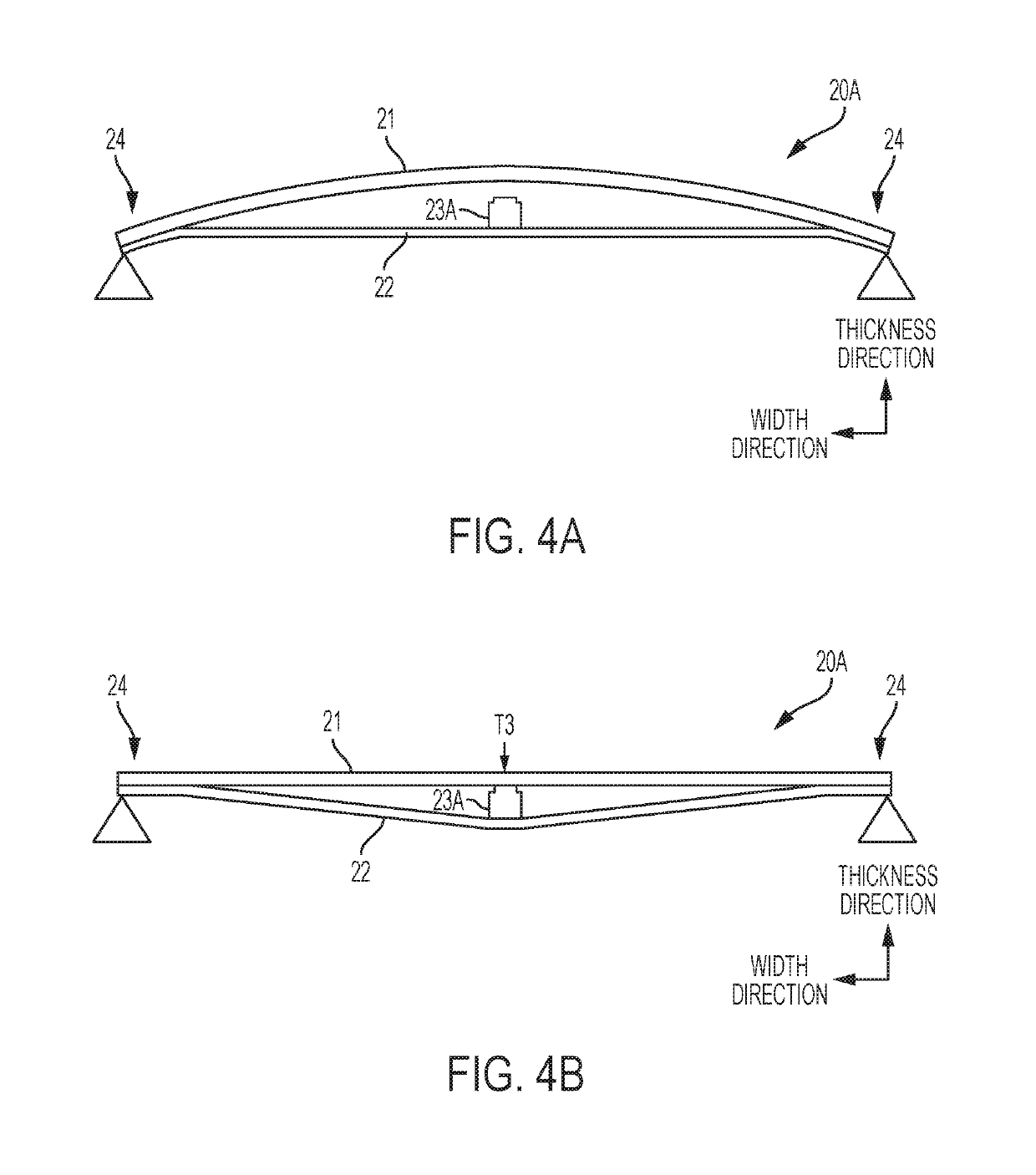
[0049]FIG. 4(A) is a side view illustrating a state where a pressing force is not applied to a vibrating device 20A according to the second embodiment. The vibrating device 20A includes a diaphragm 21, a piezoelectric film 22 and a spacer 23A. The spacer 23A has a dimension smaller than a spacing between the diaphragm 21 and the piezoelectric film 22 in the case where the spacer 23A is not provided, and is fixed to either the piezoelectric film 22 or the diaphragm 21 using an adhesive or the like. In the preferred embodiment, the spacer is fixed to the piezoelectric film 22. As a result, where the pressing force is not applied to the vibrating device 20A, the spacer 23A is not in contact with the diaphragm 21 and the piezoelectric film 22 is flat.

[0050]FIG. 4(B) is a side view illustrating a state where a pressing force is applied to the vibrating device 20A according to the second embodiment. When a...

third embodiment

[0053]Next, a vibrating device according to the present invention will be described with reference to FIGS. 5(A) and 5(B). The vibrating device 20B includes a diaphragm 21B, a piezoelectric film 22B, a spacer 23B and fixed portions 24B. As in the foregoing embodiments, the diaphragm 21B and the piezoelectric film 22B are connected at opposed fixed end areas 24B. The unstressed shape of the diaphragm 21B and the prestressed state of the piezoelectric film 22B are chosen to ensure that the diaphragm 21B lies in a flat plane before any excitation voltage is applied to the piezoelectric film 22B. More specifically, an initial shape of the diaphragm 21B in a state where the diaphragm 21B is not connected with the piezoelectric film 22B is a downwardly protruding shape. The tensile force of the piezoelectric film 22B is set such that the diaphragm 21B is deformed into a flat shape by the tensile force applied by the piezoelectric film 22B and an external force applied by the spacer 23B.

[0...

fourth embodiment

[0057]Next, a vibrating device according to the present invention will be described with reference to FIGS. 6(A) and 6(B). The vibrating device 20C includes a diaphragm 21C, a piezoelectric film 22C, spacers 23C and 24C and fixed portions 25C. The diaphragm 21C and the piezoelectric film 22C are connected to each other at the opposed fixed end areas 24C and an initial shape of the diaphragm 21C and a tensile force of the piezoelectric film 22C are set such that the diaphragm 21C maintains a flat shape without curving. Fixed portions 25C protrude downward from the fixed end areas 24C. The spacers 23C and 24C are aligned at predetermined intervals in the width direction of the vibrating device 20C (i.e., the horizontal direction in FIG. 6(B)), and contact with a lower surface of the diaphragm 21C and an upper surface of the piezoelectric film 22C to ensure a predetermined gap between the diaphragm 21C and the piezoelectric film 22C. Hence, the piezoelectric film 22C is pushed downward...


PUM


Abstract

A tactile feedback device includes a vibrating device and a touch sensor. The vibrating device comprises a flexible diaphragm and a film which deforms in response to the application of electrical energy thereto, the film being attached to the flexible diaphragm at two spaced locations with a major surface of the film facing a major surface of the flexible diaphragm. The vibrating device further includes a spacer located between the two spaced locations and ensuring that the major surface of the flexible diaphragm is spaced from the major surface of the film. The touch sensor is coupled to the diaphragm and generates an output signal in response to a touch operation. Means are provided to apply electrical energy to the film in response to the output signal.

Description

CROSS REFERENCE TO RELATED APPLICATIONS[0001]The present application is a continuation of International application No. PCT / JP2015 / 065983, filed on Jun. 3, 2015, which claims priority to Japanese Patent Application No. 2014-118332, filed on Jun. 9, 2014, the entire contents of each of which are incorporated herein by reference.TECHNICAL FIELD[0002]The present disclosure relates to a vibrating device including a diaphragm which is caused to vibrate when a driving voltage is applied to a piezoelectric film attached thereto, and a tactile feedback device which transmits the vibration of the vibrating device as tactile feedback to a user.BACKGROUND ART[0003]A vibrating device which includes a diaphragm vibrated by driving a piezoelectric film is used in a flat speaker or a haptics device (a tactile sense presenting device) as described, for example, in WO2012-0157691.[0004]FIG. 9(A) is a side view of a vibrating device 101 employing a conventional configuration, and FIG. 9(B) is a top v...

Claims


Application Information

Patent Timeline
Patent Type & Authority Patents(United States)
IPC IPC(8): G06F3/01H01L41/053H01L41/08B06B1/06G06F3/041
CPCG06F3/016B06B1/0688G06F3/041H01L41/053H01L41/081G06F3/0414G06F2203/04103H10N30/88H10N30/10513
Inventor HASHIMOTO, JUNICHI
Owner MURATA MFG CO LTD
Why Eureka
Try Eureka