
Fluidic lens with electrostatic actuation

a fluidic lens and electrostatic actuator technology, applied in optics, instruments, machines/engines, etc., can solve the problems of inconvenient form-factor of the whole system, difficulty in providing enough refractive index difference between the two liquids to provide adequate light-ray bending ability, and system disadvantage of remote location of pressurized fluid sources

Inactive Publication Date: 2007-11-15
HOLOCHIP
View PDF42 Cites 138 Cited by
  • Summary
  • Abstract
  • Description
  • Claims
  • Application Information

AI Technical Summary

Benefits of technology

[0079] As shown in FIGS. 2C-2D, the fluidic lens may be a single membrane 202 with a single lens area 208 that curves under fluid pressure. Alternatively, as shown in FIGS. 2E-2G, capacitive fluidic lenses according to embodiments of the present invention may be arranged in either a single lens configuration where there is one flexible bulging membrane 202 and a rigid base 203, or with two flexible bulging membranes 202A, 202B mounted back to back. The single lens of FIGS. 2A-2B may have a smaller package, while the double lens of FIG. 2B may have twice the optical power. It is possible to form a fluidic lens structure using two halves of the type shown in FIGS. 2A-2B to produce a double action fluidic lens.
[0203] First and second transparent inner membranes 3412, 3414 cover opposite sides of the central aperture 3401 in the mid-plane spacer 3406. Fluid fills an upper lens section bounded by the upper recess 3418, the upper flex seal 3422, upper membrane 3410 and first inner membrane 3412. Fluid fills a lower lens section bounded by the lower recess 3420, the lower flex seal 3424, lower membrane 3416 and second inner membrane 3414. A vent hole 3428 allows air to flow freely in and out of a space between the two inner membranes 3412, 3414. A filler hole 3408 communicates with both the upper and lower recesses 3418, 3420 to permit simultaneous filling of both lens sections.

Problems solved by technology

Although this yields a conveniently compact system, it is difficult to provide enough refractive index difference between the two liquids to provide adequate light-ray bending ability.
Although improved, that system still suffers from the disadvantage that the pressurized fluid source is located remotely.
This makes the form-factor of the whole system inconvenient.

Method used


Image

  • Fluidic lens with electrostatic actuation
  • Fluidic lens with electrostatic actuation
  • Fluidic lens with electrostatic actuation

Examples


Embodiment Construction

[0066] Although the following detailed description contains many specific details for the purposes of illustration, anyone of ordinary skill in the art will appreciate that many variations and alterations to the following details are within the scope of the invention. Accordingly, the exemplary embodiments of the invention described below are set forth without any loss of generality to, and without imposing limitations upon, the claimed invention.

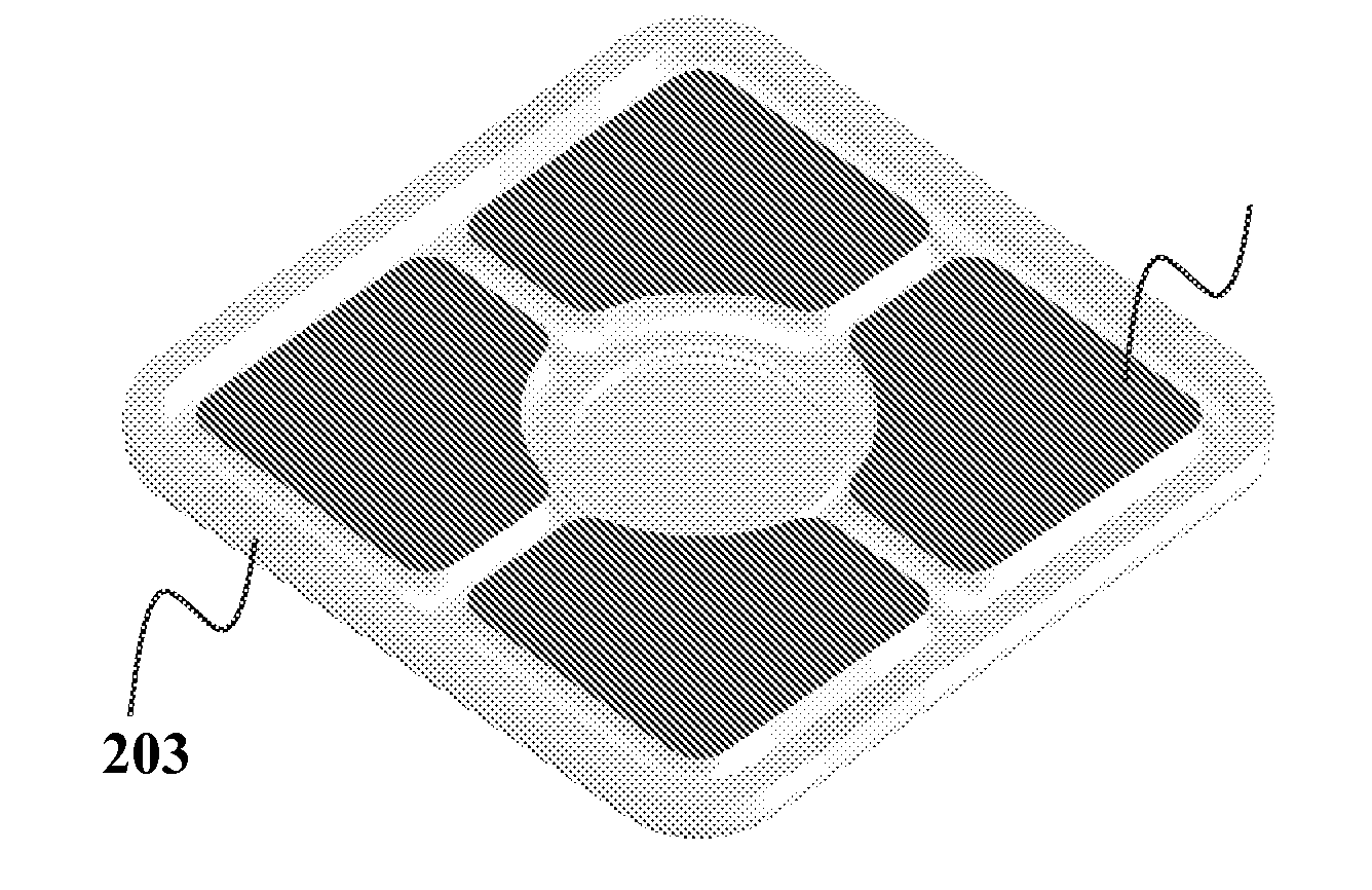
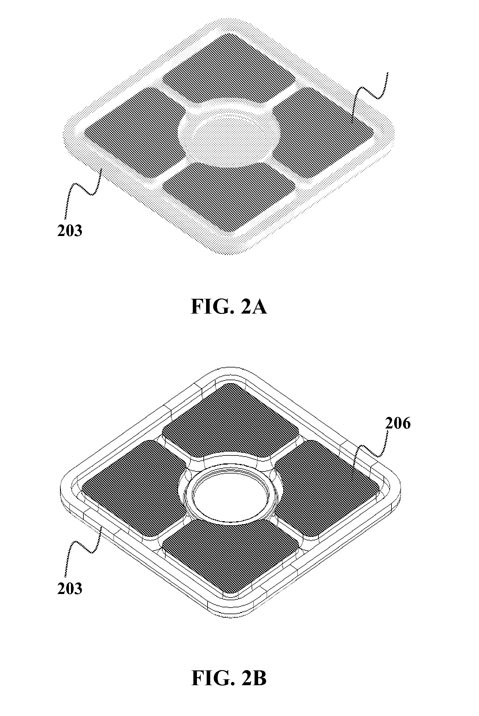
[0067] Alternative fluidic optical devices are described in commonly assigned U.S. provisional patent application 60 / 680,632, filed May 14, 2005, 60 / 683,072, filed May 21, 2005, 60 / 703,827, filed Jul. 29, 2005 and 60 / 723,381, filed Oct. 3, 2005, which are incorporated herein by reference. Such fluidic optical devices include a device skeleton having an aperture and a reservoir in fluid communication with the aperture. The aperture and reservoir are integral to the skeleton. A transparent fluid is enclosed within the aperture and reservoir....


PUM


Abstract

An electrostatically actuated fluidic device capable of providing a variable focal length lens is disclosed. The device includes an elastic capacitor section, an elastic lens section in fluid communication with the capacitor section, the elastic lens section being characterized by a focal length and a fluid capable of fluid motion disposed at least partially in the capacitor and lens sections. A voltage may be applied to the capacitor section causing it to deform, which causes a portion of the fluid to flow into or out of the lens section. As a result, a change in volume of fluid in the lens section causes it to deform resulting in a variation in the focal length of the lens section.

Description

CLAIM OF PRIORITY [0001] This application claims the benefit of priority of the U.S. Provisional Patent Application No. 60 / 747,181, entitled “ELECTROSTATIC ACTUATION OF FLUIDIC LENS”, filed May 12, 2006, which is hereby incorporated by reference. This application is a continuation-in-part of commonly assigned U.S. patent application Ser. No. 11 / 383,216 entitled FLUIDIC OPTICAL DEVICE, and published as US Patent Application Publication 20070030573, the contents of which are incorporated herein by reference. This application claims the benefit of priority of U.S. patent application Ser. No. 11 / 383,216 and the benefit of priority of all applications to which U.S. patent application Ser. No. 11 / 383,216 claims the benefit of priority, including U.S. Provisional Patent Application 60 / 680,632 to Robert G. Batchko et al entitled “FLUIDIC OPTICAL DEVICES”, filed May 14, 2005, the entire disclosures of which are incorporated herein by reference, U.S. Provisional Patent Application 60 / 683,072 ...

Claims


Application Information

Patent Timeline
Patent Type & Authority Applications(United States)
IPC IPC(8): G02B1/06
CPCG02B26/004G02B3/14F03G7/005
Inventor BATCHKO, ROBERT G.MANSELL, JUSTINSZILAGYI, ANDREI
Owner HOLOCHIP
Learn More