
Vantilating system and method for controlling the same

a technology of ventilating system and ventilation system, which is applied in the direction of ventilating system, lighting and heating apparatus, heating type, etc., can solve the problems of dermatitis, cancer, limited outdoor air supply the inability to ventilate the room in a unit time period, so as to improve the ventilating capability of the ventilating system

Inactive Publication Date: 2007-11-15
CHOI HO SEON +3
View PDF15 Cites 21 Cited by
  • Summary
  • Abstract
  • Description
  • Claims
  • Application Information

AI Technical Summary

Benefits of technology

"The present invention is a ventilating system and method for controlling it that can ventilate a room when it is polluted heavily. The system includes a duct for making a room and an outside of the room in communication, a ventilator connected to the duct for discharging room air and introducing outdoor air, and window controllers for opening / closing windows. The system also includes a sensor for measuring the content of volatile organic compounds in the room air, and a controller for controlling the ventilator and window controllers based on the measured conditions. The ventilating method and rate of ventilation are determined based on the content of volatile organic compounds in the room air. The system can improve ventilating capabilities without adding larger ventilating system and ducts. The invention provides a solution for ventilating a room in a more efficient and effective way."

Problems solved by technology

It is known that such volatile organic compounds cause dermatitis, and cancer.
However, sizes of the air supply, and discharge ducts, and outputs of the air supply fan and the air discharge fan are fixed already, an amount of outdoor air supplyable in a unit time period, and an amount of room air dischargeable to an outside of the room in a unit time period, are limited.
Therefore, in a case the room air is polluted heavily, the room can not be ventilated, quickly.
However, in this case bulky ventilating system and ducts impedes easy mounting thereof.

Method used


Image

  • Vantilating system and method for controlling the same
  • Vantilating system and method for controlling the same
  • Vantilating system and method for controlling the same

Examples


Embodiment Construction

[0036] Reference will now be made in detail to the preferred embodiments of the present invention, examples of which are illustrated in the accompanying drawings. Wherever possible, the same reference numbers will be used throughout the drawings to refer to the same or like parts.

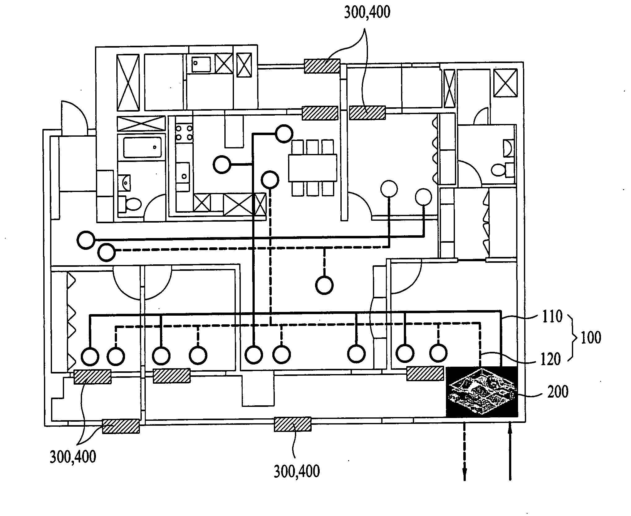
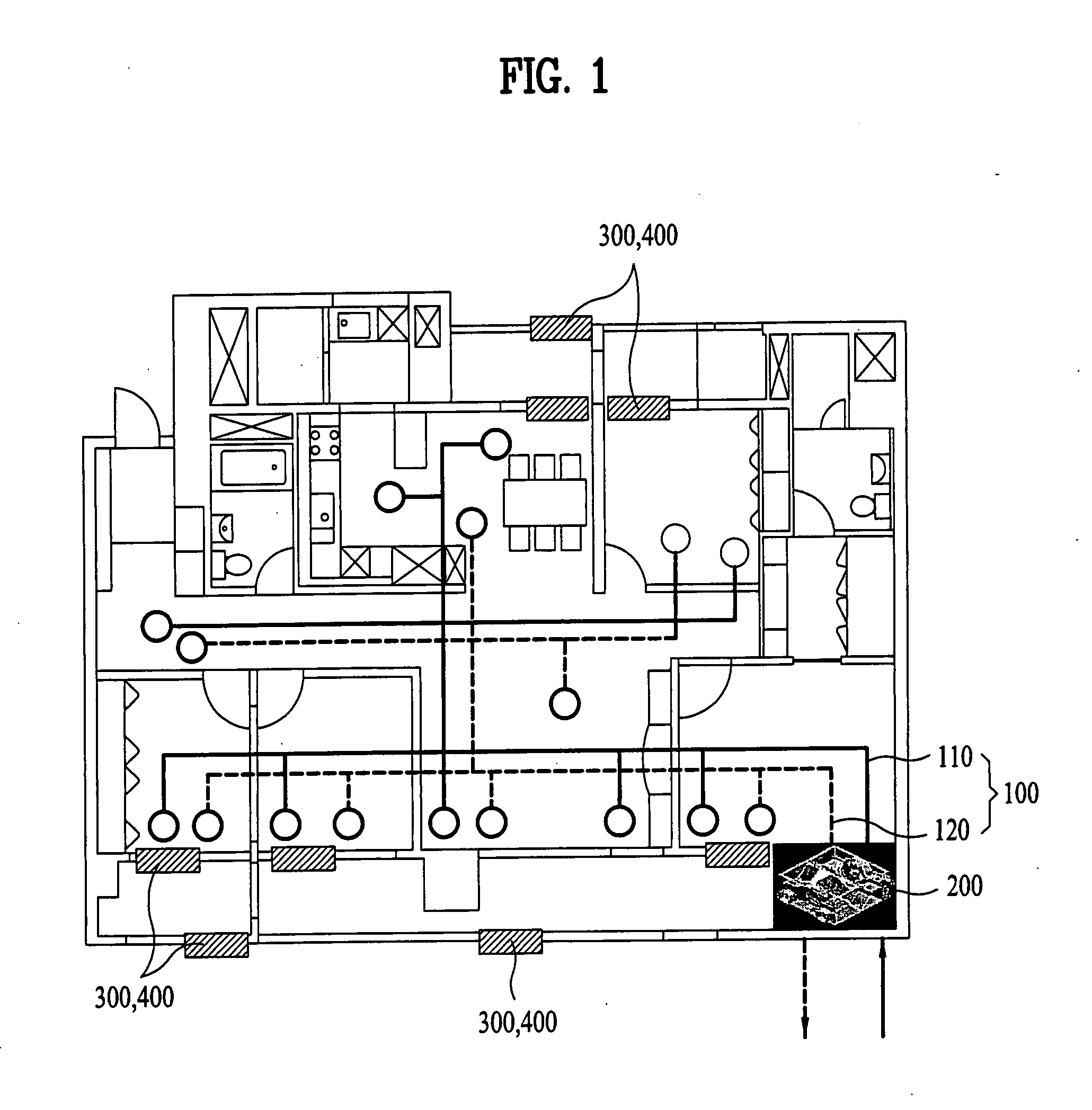
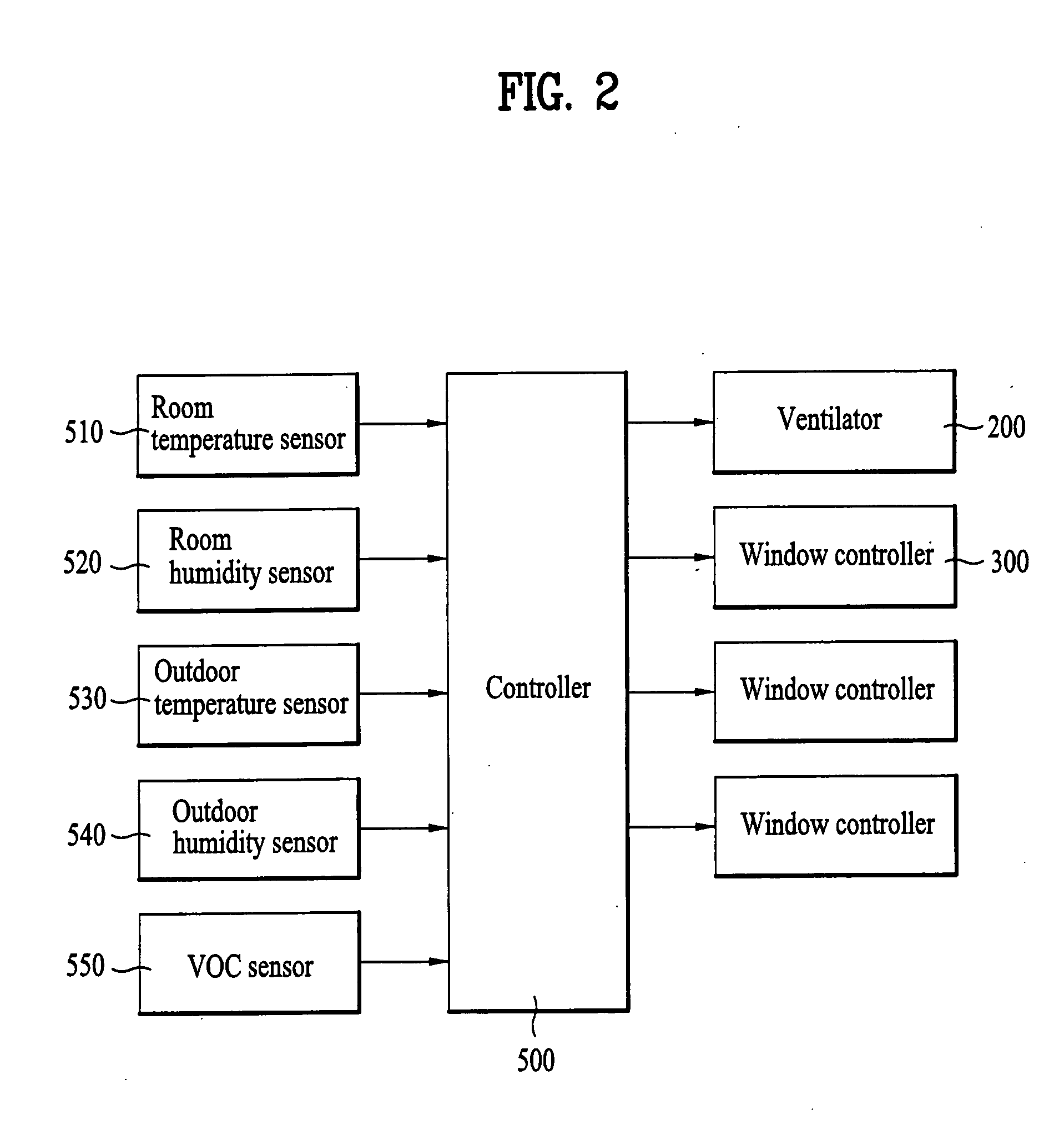
[0037] Referring to FIGS. 1 and 2, the ventilating system of the present invention includes a duct 100 making a room and an outside of the room in communication, a ventilator 200 connected to the duct 100, for discharging room air to an outside of the room through the duct 100, and supplying outdoor air to the room, window controllers 300, and 400 mounted to the windows W1, and W2 for opening / closing the windows W1, and W2 respectively, and a controller 500 for controlling the ventilator 200 and the window controllers 300, and 400, for ventilating the room.

[0038] Referring to FIG. 1, the duct 100 includes an air supply duct 110 for supplying outdoor air to rooms, and a discharge duct 120 for discharging r...


PUM


Abstract

Ventilating system for introducing outdoor air and discharging room air, and method for controlling the same, the ventilating system including a duct for making a room and an outside of the room in communication, a ventilator connected to the duct for discharging room air to an outside of the room, and supplying outdoor air to the room through the duct, a window controller provided to each window for opening / closing the window individually, and a controller for controlling the ventilator and the window controller for ventilating the room. The method for controlling a ventilating system includes the steps of measuring conditions of room air and outdoor air, determining a ventilating method and a ventilating rate according to the measured conditions, and ventilating the room by opening / closing the window automatically, and putting a ventilator into operation according to a result of determination.

Description

CROSS-REFERENCE TO RELATED APPLICATION [0001] This application is a Divisional of co-pending application Ser. No. 11 / 147,431 filed on Jun. 8, 2005, and for which priority is claimed under 35 U.S.C. §120; and this application claims priority of Application No. P2005-0012316 filed in Korea on Feb. 15, 2005 under 35 U.S.C. § 119; the entire contents of all are hereby incorporated by reference.BACKGROUND OF THE INVENTION [0002] 1. Field of the Invention [0003] The present invention relates to ventilating systems, and more particularly, to a ventilating system for introducing outdoor air and discharging room air, and a method for controlling the same. [0004] 2. Discussion of the Related Art [0005] A ventilating system is provided to a general house or an apartment for ventilating rooms. Such a ventilating system is provided with a duct that forms a moving passage of air. The ventilating system is provided with, in general, an air supply fan and an air discharge fan, and the duct is, in g...

Claims


Application Information

Patent Timeline
Patent Type & Authority Applications(United States)
IPC IPC(8): F24F13/00F24F7/003
CPCF24F11/0001F24F11/0012F24F2007/004F24F2011/0027Y02B30/78F24F2011/0026F24F11/30F24F2110/10F24F2110/70F24F2110/72Y02B30/70F24F11/76F24F7/003F24F7/06F24F13/1426F24F11/89F24F11/64F24F2110/65F24F2013/1433F24F2013/1446F24F2110/20
Inventor CHOI, HO SEONLEE, JU YOUNKIM, HO JUNGCHOI, IN HO
Owner CHOI HO SEON
Learn More